

This guide applies to DCL explosion-proof series/general series/quick-open series switching actuators with the following model numbers:
- General Series: DCL-05/DCL-10/DCL-20/DCL-40/DCL-60/DCL-100/DCL-160/DCL-250
- Explosion-proof Series: DCL-Ex05/DCL-Ex10/DCL-Ex20/DCL-Ex40/DCL-Ex60
- Quick Open Series: DCL-K05/DCL-K10/DCL-K20/DCL-K40/DCL-K100
1, common faults and troubleshooting methods.
| 故障 | 可能的原因 | 排除方法 |
|---|---|---|
| 执行器在初次启动时不会打开或关闭 | 1. 接线不正确 | 按照执行器的接线图核对接线是否正确? |
| 2. 供电电源不正确 | 确认供电电源的输出电压为执行器额定电压的±10%,输出电流为执行器额定电流的3倍。 | |
| 3. 控制开关或控制继电器异常 | 使用万用表测量执行器开关控制端的输入电压,确认是否符合预期? | |
| 4. 控制系统匹配问题 | 使用机械开关测量执行器功能,如果执行器运行正常,核对控制系统的输出逻辑是否符合预期? | |
| 5. 多个执行器或执行器和其它设备并联 | 开关型执行器是通过启动电容完成启动的,和其它设备并联将对启动电容的容值产生影响。所以,开关型执行器只能使用单路控制,不能并联。 | |
| 执行器只能开启或关闭 | 1. 接线不正确 | 1. 使用机械开关测量执行器功能,如果执行器运行正常,核对控制系统的输出逻辑是否符合预期? 2. 按照执行器的接线图核对接线是否正确? |
| 2. 全开/全关 凸轮设置不当 | refer to (another document)《如何设置开关型电动阀门》,正确设置凸轮位置。 | |
| 执行器在行程中间停止 | 1. 阀门卡滞 | 检查阀门是否存在卡滞,消除卡滞,并在执行器过载保护冷却后重试。 |
| 2. 流体介质中潜在的固体物导致阀门卡滞。 | 检查流体介质中是否存在固体物卡滞阀门的情况,消除阀门卡滞,并在执行器过载保护冷却后重试。 | |
| 3. 全开/全关 挡块设置不当 | refer to (another document)《如何设置开关型电动阀门》,正确设置挡块位置。 | |
| 使用手柄,无法转动执行器 | 1. 流体介质中潜在的固体物导致阀门卡死。 | 检查流体介质中是否存在固体物卡滞阀门的情况,消除阀门卡滞,并在执行器过载保护冷却后重试。 |
| 2. 阀门卡死 | 检查阀门是否存在卡滞,消除卡滞,并在执行器过载保护冷却后重试。 | |
| 3. 执行器减速机构损坏。 | 从阀门上拆下执行器,转动手柄。如果不能转动,使用新的执行器更换。 | |
| 位置反馈信号无输出 | 1. 开关接线不正确 | 按照执行器的接线图核对接线是否正确? |
| 2. 全开/全关 凸轮设置不当 | refer to (another document)《如何设置开关型电动阀门》,正确设置凸轮位置。 | |
| 3. 过流导致位置反馈信号开关损坏。 | 1. 参照《如何设置开关型电动阀门》,检查全开/全关 凸轮是否压实位置反馈开关? 2. 测量位置反馈回路是否接通? |
2、Please check whether the application working condition meets the parameter requirements.
Electric actuators can fail due to improper use or under the wrong application conditions. Long-term trouble-free operation of the actuator will be ensured under the application conditions defined in the product specification.
- Supply voltage:The voltage of the power supply must be within the rated operating voltage of the actuator. Overvoltage or undervoltage may result in reduced actuator life.
- Supply current:Since the starting current of the motor is much larger than the rated current. To ensure reliable operation of the actuator, use a power supply with an output current capacity more than three times the rated current of the actuator.
- Temperature:Ensure that the actuator operates within the rated operating temperature range. Use of the actuator in environments outside of the rated operating temperature range may result in malfunction or reduced service life of the actuator, and ultimately, failure of the actuator.
- Environment:DCL switching actuators have an IP67 weatherproof rating. Generally suitable for indoor or outdoor applications. Provides a degree of protection against rain and splashing water. Protecting the actuator from rain, snow, ice, and UV (sunlight) usually extends the life of the product. Very corrosive environments may cause premature failure of electronic equipment. Do not use non-explosion proof series actuators in explosion proof environments.
- Energized persistence rate:The DCL switching actuator has an energization duration rate of 70% (42 seconds of operation per minute and must be turned off for 18 seconds), exceeding the 70% energization duration rate will cause the motor to go into overheat protection.
3、Check whether the wiring of the actuator is correct or not
Type A: with limit position switches (active contacts)
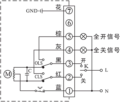
Through the switching circuit to realize the "on", "off" operation, and output a set of full open and full closed active signal.
Wiring Instructions:
1. Terminal 1 is connected to the center line of the power supply;
2、 Power supply phase line and terminal 2 connected for "off" operation;
3. The power supply phase line is "on" when it is connected to terminal 3;
4, power supply phase line and terminal 2 connected and "off" operation in place, terminal 4 connected to the "full off signal" indicator light;
5, power supply phase line and terminal 3 connected and "open" operation in place, terminal 5 connected to the "full open signal" indicator light;
6. Terminal 7 Ground wire.
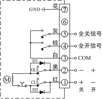
Type B: with intermediate position switch (passive contact)
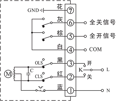
Through the switching circuit to realize the "on", "off" operation, and output a set of full open and full closed passive signal.
Wiring Instructions:
1. Terminal 1 is connected to the center line of the power supply;
2、 Power supply phase line and terminal 2 connected for "off" operation;
3. The power supply phase line is "on" when it is connected to terminal 3;
4. Terminal 4 is the common terminal of passive contact;
5. When "open" operation is in place, terminal 5 outputs "full open signal".
6、When the "OFF" operation is in place, the terminal will program the "Full Off Signal";
7. Terminal 7 ground wire.
Type C: with 1KΩ (or 500Ω) potentiometer
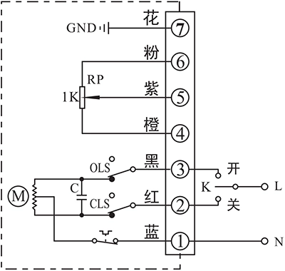
The switching circuit realizes "on" and "off" operation and outputs a resistance signal corresponding to the opening position.
Wiring Instructions:
1. Terminal 1 is connected to the center line of the power supply;
2、 Power supply phase line and terminal 2 connected for "off" operation;
3. The power supply phase line is "on" when it is connected to terminal 3;
Terminal 4 is the low end of the potentiometer, when "open" operation, the resistance between terminal 4 and terminal 5 increases with the increase of the opening degree;
5. Terminal 5 is the potentiometer movable arm;
Terminal 6 is the high end of the potentiometer, when "open" operation, the resistance between terminal 6 and terminal 5 decreases with the increase of the opening degree;
7. Terminal 7 ground wire.
Type D: with potentiometer and passive contact position switches
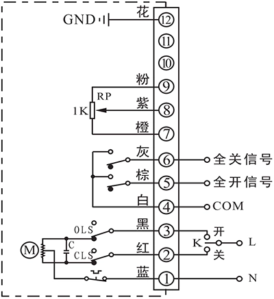
Through the switching circuit to realize the "on", "off" operation, and output and open position corresponding to the amount of resistance signals, while outputting a set of fully open and fully closed passive signals.
Wiring Instructions:
1. Terminal 1 is connected to the center line of the power supply;
2、 Power supply phase line and terminal 2 connected for "off" operation;
3. The power supply phase line is "on" when it is connected to terminal 3;
4. Terminal 4 is the common terminal of passive contact;
5, "open" operation in place, terminal 5 output "full open signal";
6、When the "Off" operation is in place, the "Full Off Signal" will come out from the terminal.
Terminal 7 is the low end of the potentiometer, when "open" operation, the resistance between terminal 7 and terminal 8 increases with the increase of the opening degree;
8. Terminal 8 is the potentiometer movable arm;
Terminal 9 is the high end of the positioner, when "open" operation, the resistance between terminal 9 and terminal 8 decreases with the increase of the opening degree;
10. Terminal 12 grounding wire.
Type F: with position transmitter
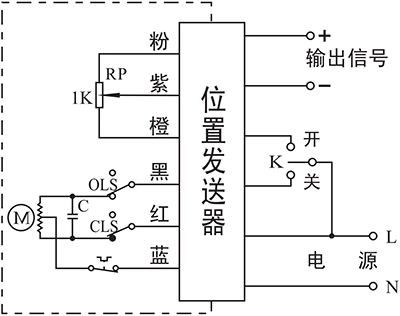
Through the switching circuit to realize the "on", "off" operation, and output a set of full open and full closed active signal.
Wiring Instructions:
1. "N" of the "Power" input is connected to the center line, and "L" is connected to the phase line.
2、When the phase line "L" of the input of "power supply" is connected to "off", it will run in the direction of off, and when it is connected to "on", it will run in the direction of on. When "L" is connected to "OFF", it runs in the OFF direction;
3. The "output signal" end is connected to the negative pole of the DC ammeter, and the "+" is connected to the positive pole of the DC ammeter.
Type G: DC control circuit with passive contact switches
According to the unidirectional conductivity of the diode, by reversing the positive and negative poles of the DC power supply, it realizes the "on" and "off" operation and outputs a set of passive signals of full on and full off.
Wiring Instructions:
Terminal 1 is connected to the positive pole of the power supply, and terminal 2 is connected to the negative pole of the power supply for "off" operation; lemon 2 is connected to the positive pole of the power supply, and terminal 1 is connected to the negative pole of the power supply for "on" operation;
2、 Terminal 3 is the common terminal of passive contact;
3. When the "open" operation is in place, the terminals confirm the "full open signal".
4、When "Off" operation is in place, terminal 5 outputs "full off signal".
5. Terminal 7 Ground wire.
Type H: Three-phase AC control circuit with passive contact switches
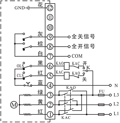
Through the external phase inversion circuit, the motor is reversed to realize "on" and "off" operation and output a set of passive signals for full on and full off.
Wiring Instructions:
Terminals 1, 2 and 3 are connected to three-phase alternating current to realize forward and reverse rotation of the motor through external phase reversal circuit;
2. Terminal 4 is the common terminal of the external control circuit;
3. Terminal 5 is the "off" operation control;
4. Terminal 6 is "on" operation control;
5. Terminal 7 is the common terminal of passive contact;
6、When the "open" operation is in place, the terminal Han out of the "full open signal".
7、When "OFF" operation is in place, terminal 9 outputs "full off signal";
8. Terminal 12 ground wire.


 Egong.com.cn 42018502006527 No.