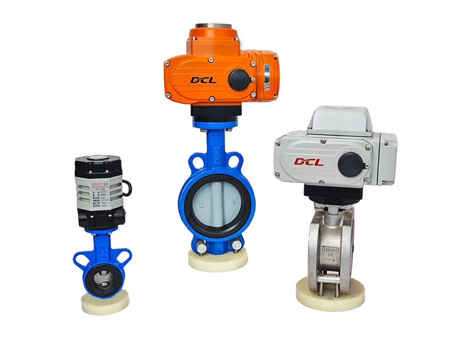
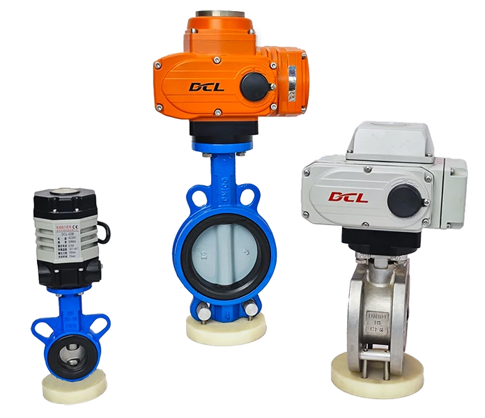
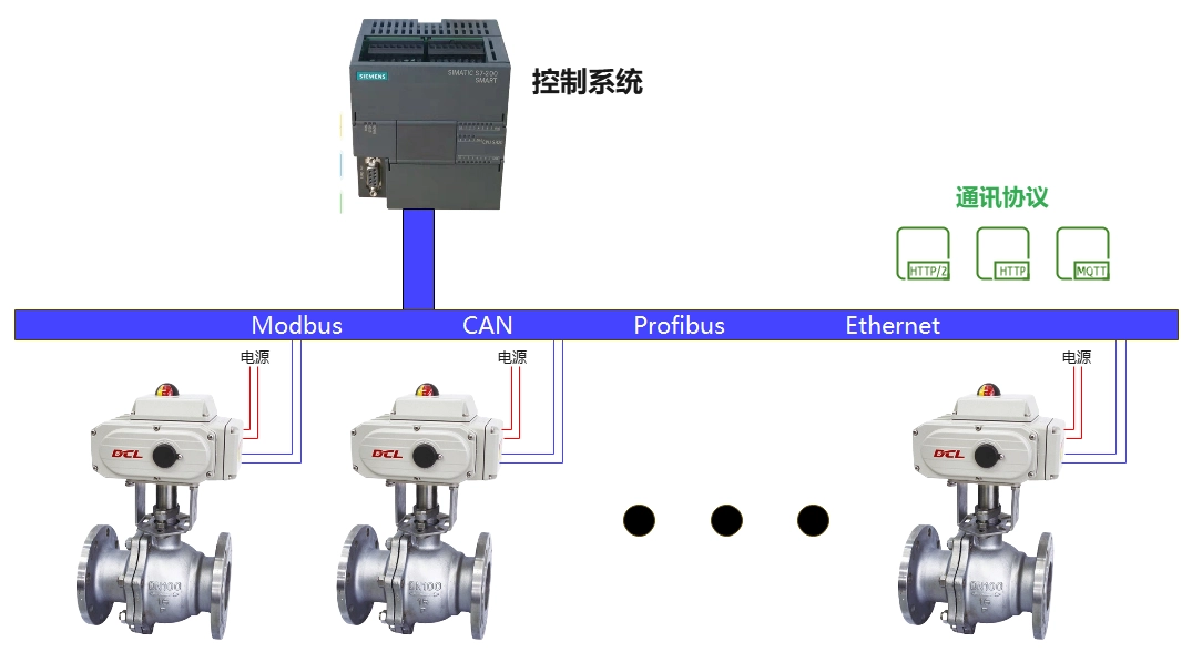
When you install DCL with bus function for electronically controlled valves on the pipeline, you can control a group of electronically controlled valves via bus (Modbus, CAN, Ethernet, Profibus), thus realizing synchronous control of valve clusters.
Using the bus Control of DCL actuators
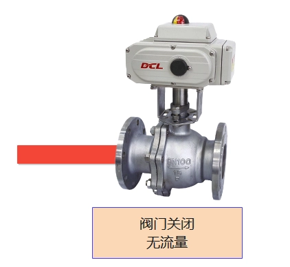
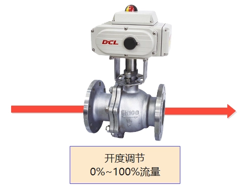
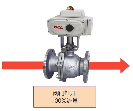
The control system sends opening control commands to the actuator through the bus communication protocol. The actuator follows the bus command to drive the valve to the specified opening.
If a bus error occurs, the valve is actuated to fully open, fully close, or maintain the valve position at the time of the bus error, depending on the user setting.
If the power supply to the power line stops while the actuator is driving the valve, the actuator stops driving and the motorized valve maintains its current position.
NOTE: The above circuit diagram shows the function of a switching actuator (motorized valve) in its simplest form. In practical applications, additional protection devices such as fuses and current limiters should also be considered.


 Egong.com.cn 42018502006527 No.