When you install a DCL switching type electronically controlled valve on your pipeline, you can control your electronically controlled valve with a relay, switch, or PLC (DCS) along the way to open or close the fluid.
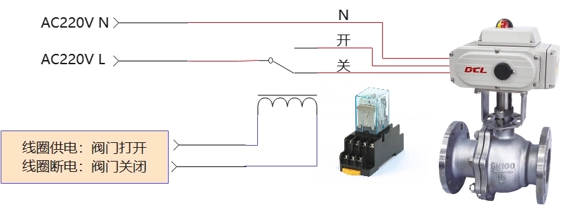
Control of DCL actuators using relays/PLC/DCS
When the L line is switched to the OFF input terminal through the relay, the actuator drives the valve closed. When driven to the fully closed position, the actuator stops driving and the motorized valve remains fully closed.
When the L line is switched to the open input terminal through the relay, the actuator drives the valve open. When driven to the fully open position, the actuator stops driving and the motorized valve remains in the fully open position.
If the power supply to the AC220V L line stops while the actuator is driving the valve, the actuator stops driving and the motorized valve maintains its current position.
When the actuator you selected is equipped with a heated dehumidifier, keep the power supply on the AC220V L line after driving the actuator to the fully open/closed position.
NOTE: The above circuit diagram shows the function of a switching actuator (motorized valve) in its simplest form. In practical applications, additional protection devices such as fuses and current limiters should also be considered.
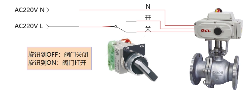
Control of DCL actuators using mechanical switches
When the L line is switched to the OFF input terminal through the relay, the actuator drives the valve closed. When driven to the fully closed position, the actuator stops driving and the motorized valve remains fully closed.
When the L line is switched to the open input terminal through the relay, the actuator drives the valve open. When driven to the fully open position, the actuator stops driving and the motorized valve remains in the fully open position.
If the power supply to the AC220V L line stops while the actuator is driving the valve, the actuator stops driving and the motorized valve maintains its current position.
When the actuator you selected is equipped with a heated dehumidifier, keep the power supply on the AC220V L line after driving the actuator to the fully open/closed position.
NOTE: The above circuit diagram shows the function of a switching actuator (motorized valve) in its simplest form. In practical applications, additional protection devices such as fuses and current limiters should also be considered.


 Egong.com.cn 42018502006527 No.