

National Standard for Electric Actuators: JB/T 8219-2016 General and Intelligent Electric Actuators for Industrial Process Control Systems (National Standard for Electric Actuators)
CONTENTS
preamble
1 Scope 1
2 Normative references 1
3 Terminology and definitions 1
4 Product classification and basic parameters 2
4.1 Product classification 2
4.2 Basic parameters 2
5 Basic functions of intelligent actuators 3
5.1 Display functions 3
5.2 Parameter setting function 3
5.3 Field configuration functions 3
5.4 Fault self-diagnosis and alarm functions 4
5.5 Communication functions 4
5.6 Other functions 4
6 Requirements 4
6.1 Basic performance requirements 4
6.2 Performance Requirements for Impact Volume Impacts 6
6.3 Appearance 8
6.4 Enclosure protection class 8
6.5 Explosion protection 8
7 Test methods 8
7.1 Test conditions 8
7.2 General provisions for testing 9
7.3 Fundamental errors 9
7.4 Basic deviation of the position output signal 9
7.5 Returns 10
7.6 Dead zones 10
7.7 Time lag 10
7.8 Rated travel time error 10
7.9 Starting characteristics 11
7.10 Repeatability error of travel control mechanism 11
7.11 Insulation resistance 11
7.12 Dielectric strength 11
7.13 Temperature rise 11
7.14 Long-term operational stability 11
7.15 Maximum and Minimum Control Torque and Thrust Repeatability Errors 11
7.16 Manual-electric switching mechanism 12
7.17 Basic Functions of Smart 12
7.18 Noise 13
7.19 Stepless (variable frequency) speed control 13
7.20 Impact of ambient temperature 13
7.21 Effects of heat and humidity
7.22 Effects of supply voltage 14
7.23 Effects of mechanical vibration 14
7.24 Environmental impacts of transportation
7.25 Radiofrequency electromagnetic field radiation immunity 15
7.26 Electrical fast transient pulse group immunity 15
7.27 Surge (shock) immunity 5
7.28 Electrostatic discharge immunity 15
7.29 Industrial frequency magnetic field immunity 15
7.30 Observations 16
7.31 Enclosure protection class 16
7.32 Explosion protection 16
8 Inspection rules 16
8.1 Factory inspection 16
8.2 Type examination 16
9 Marking, packaging and storage 17
9.1 Logo 17
9.2 Packaging 18
9.3 Storage 18
Table 1 Technical indicators of basic performance 4
Table 2 Technical indicators of impact quantities 6
Table 3 Test items 16
Preface
This standard is drafted according to the rules given in GB/T1.1-2009.
This standard replaces JB/T8219-1999 "industrial process measurement and control system with electric actuators", and JB/T 8219-1999 compared to the main technical changes are as follows:
--Changed the standard name;
--Normative references have been updated (see chapter 2).
--In the classification of products, the classification according to the relationship between the input and output of the actuator in the original standard is changed to the classification according to the control mode of the actuator, which is divided into switching actuator and regulating actuator (see 4.1.2); the classification according to the driving mode of the motor is added (see 4.1.4); and the indicators of "damping characteristics, clearance and idling amount" (see 4.2 of the 1999 edition) are removed. The indexes of "damping characteristics, clearance and idler volume" (see 4.2 of the 1999 edition) have been removed.
--Amend former Standard 3.7 "Proportional actuator input signals" to preferred input signals for modulating actuators and preferred input signals for switching actuators (see 4.2.5).
--The basic functions of intelligent actuators have been added (see chapter 5).
--The accuracy level is revised from "Class 1, Class 2.5, Class 5" to "Class 0.5, Class 1.0, Class 1.5, Class 2.5" in the original standard (see Table 1); "Proportional electric actuator" and "Integral electric actuator" are revised to "Regulating actuator" and "Switching actuator" in the original Table 1. Proportional electric actuator" and "integral electric actuator" in the original Table 1 are revised to "regulating actuator" and "switching actuator". "; and
--Added "Maximum and minimum control torque and thrust repeatability error", "Basic functions of intelligent type", "Radio frequency electromagnetic field radiation immunity", "Electrical fast transient pulse group immunity", "Surge (shock) immunity", "Electrostatic discharge immunity", and so on to the requirements. "Radio-frequency electromagnetic field radiation immunity", "Electrical fast transient pulse group immunity", "Surge (shock) immunity", "Electrostatic discharge immunity". (b) Requirements for "immunity to magnetic fields at industrial frequencies" (see 6.1.13, 6.1.15, 6.2.6, 6.2.7, 6.2.8, 6.2.9, 6.2.10).
--Modified or added some test methods, e.g., temperature rise (see 7.13), ambient temperature effects (see 7.20), supply voltage effects (see 7.22).
This standard is proposed by the China Machinery Industry Federation.
This standard is under the purview of the National Technical Committee for Standardization of Industrial Process Measurement, Control and Automation (SAC/TC124).
Drafting unit of this standard: Shanghai Research Institute of Industrial Automation Instrumentation, Suzhou Boryu Measurement and Control Equipment Company Limited, Wenzhou Ruiji Measurement and Control Equipment Co,Wuhan Huayi Technology Co.Yangzhou Aibode Auto-control Equipment Manufacturing Co.
Main drafters of this standard: Zheng Yong, Zhang Jianwei, Li Minghua, Li Weihua, Guo Aihua, Chen Jianguo, Chen Jun, Ge Runping, Li Limin,
Peng Qilin, Xu Zhen.
The successive versions of the standard that this standard replaces were published as:
--JB/T 8219- 1995, JB/T 8219- 1999.
General and Intelligent Electric Actuators for Industrial Process Control Systems
1 Scope
This standard specifies the industrial process control system with ordinary and intelligent electric actuator (hereinafter referred to as the actuator) product classification, requirements, test methods, inspection rules, signs, packaging and storage.
This standard applies to motor-driven actuators of various types such as angular stroke, straight stroke and multi-turn.
2 Normative references
The following documents are essential for the application of this document. For dated references, only the dated version applies to this document. For undated references, the latest version (including all change orders) applies to this document.
GB 3836.1 Explosive environment Part 1: Equipment General requirements
GB 3836.2 Explosive atmospheres Part 2: Equipment protected by explosion-proof enclosures "d".
GB 4208-2008 Enclosure protection class (IP code)
GB/T 13384 General Technical Conditions for Packaging of Electromechanical Products
GB/T17626.2 Electromagnetic compatibility Test and measurement techniques Electrostatic discharge immunity test
GB/T17626.3 Electromagnetic compatibility Test and measurement techniques RF electromagnetic field radiation immunity test
GB/T17626.4 Electromagnetic compatibility test and measurement techniques Electrical fast transient pulse group immunity test
GB/T17626.5 Electromagnetic compatibility Test and measurement techniques Surge (shock) immunity test
GB/T 17626.8 Electromagnetic compatibility test and measurement techniques Magnetic field immunity test at working frequency
GB/T18271.1-2000 Process measurement and control devices General performance evaluation methods and procedures Part 1: General principles
GB/T 25480 Basic environmental conditions and test methods for transportation and storage of instruments and meters
GB/T 26815-2011 Industrial automation instrumentation terminology Actuator terminology
3 Terminology and definitions
As defined in GB/T 26815-2011 and the following terms and definitions apply to this document.
3.1
maximum control torque
The maximum torque that can be controlled during actuator operation.
3.2
Minimum control torque
The minimum torque that can be controlled during actuator operation.
3.3
maximum control thrust
The maximum thrust that can be controlled during actuator operation.
3.4
minimum control thrust
The minimum thrust that can be controlled during actuator operation.
4 Product classification and basic parameters
4.1 Product Classification
4.1.1 Classification by type of output displacement
According to the type of actuator output displacement is divided into:
-Corner travel;
--Straight stroke;
--More turns.
4.1.2 Classification by control mode
Classified by actuator control:
--Switching type;
--Regulated.
4.1.3 Classification by working environment
Classified according to the operating environment of the actuator:
--Conventional;
--Explosion-proof type.
Note: Other types may be used as required.
4.1.4 Classification by motor drive mode
Classified by motor drive mode:
--Mechanical with contacts;
-- Electronic non-contact.
4.2 Basic parameters
4.2.1 Working environmental conditions
The actuator shall be capable of functioning properly under the following conditions:
--Ambient temperature: -10℃~55℃, or -20℃~60℃, or -30℃~70℃.
--Relative humidity: not greater than 95%; --Relative humidity: not greater than 95%.
--Atmospheric pressure: 86 kPa to 106 kPa.
Note: For actuators used in special environments, the working environment conditions are determined by the user in consultation with the manufacturer.
4.2.2 Dynamic conditions
The actuator operates with the following power supply:
AC: Single-phase (2202322 )V; Three-phase (380±38)V; Frequency (50±0.5)Hz; Harmonic content less than 5%.
DC: (24±2.4)V; (48±4.8)V; Ripple peak is less than 5% of the supply voltage. Note: Special power conditions are determined by the user in consultation with the manufacturer.
4.2.3 Rated load
The actuator load ratings are preferably selected from the following series:
-- Angular stroke [in N-m]: 6,16,40,100,250,600,1000,1600,2500,4000.
6,000,10,000,16,000,....
--Straight stroke [in Nm]: 250,400,600,1000,1600,2500,4000,6000,10000,16000.
25,000,40,000,60,000,....
-- Multiple revolutions [in N-m]: 16,40,100,160,250,400,600,1000,1600,2500, ....
Note: Manufacturers are permitted to select other number systems as appropriate.
4.2.4 Rated travel
The actuator stroke ratings are preferably selected from the following series:
- Angular travel [in degrees (°)]: 50,70,90,120,270, ...; ...; ...
--Straight Stroke [in millimeters (mm)]: 10,16,25,40,60,100,160,250,400,600,1000,....
-- Multiple revolutions [in revolutions (r)]: 5,7,10,15,20,40,80,120, ....
Note: Manufacturers are permitted to select other number systems as appropriate.
4.2.5 Input signals
4.2.5.1 The following input signals are preferred for modulating actuators:
DC4 mA to 20 mA.
Note: Other input signals can be selected according to user needs.
4.2.5.2 The following input signals are preferred for switching actuators:
Passive contact, DC24V, AC220V.
Note: Other input signals can be selected according to user needs.
4.2.6 Number of connections
The actuator's operating system is a reversible intermittent operating system, and the number of connections per hour is taken from the following series: 100,320,630,1200,1800 when the connection duration is 20% to 80%.
Note 1:Turn-on duration is the ratio of the actuator's motor power-on time to the motor power-off cycle, expressed as a percentage.
Note 2: The working system, continuity rate and number of connections per hour of the actuator can be specified according to the user's needs.
5 Basic functions of intelligent actuators
5.1 Display functions
Intelligent actuator can display the working parameters, operation status information, signal query, fault alarm, etc. through the human-machine interface in Chinese (or in other ways according to user requirements).
5.2 Parameter setting function
Intelligent actuator can set the working parameters such as stroke and torque, calibrate the 4mA~20mA current input signal and adjust the 4mA~20mA current output signal through the human-machine interface.
5.3 Field configuration functions
The intelligent actuator has at least the following field configuration functions:
--Switching contact mode for operation status output can be set on site;
--Control mode can be set on site for remote and local control.
5.4 Fault self-diagnosis and alarm function
Intelligent actuators can diagnose abnormal conditions (motor overheating, power supply phase failure, valve jamming, etc.) that occur during operation and can automatically display fault information locally and output alarms remotely.
5.5 Communication functions
Intelligent actuators can be equipped with optional digital communication interface to realize fieldbus communication control. The adopted fieldbus protocol products should be sent to the corresponding authoritative testing organizations for testing to confirm whether they comply with the corresponding fieldbus standards.
5.6 Other functions
Intelligent actuators are also available with the following functions:
With not less than 4-way switching contact outputs (of which not less than 2-way switching contact outputs whose status does not change after power failure).
-- Power supply phase sequence adaptive function;
-Position sensors are preferred to non-contact absolute encoders that do not require battery support;
--Torque sensors for continuous measurement of the output torque (thrust) of the actuator.
--For high-precision control and multi-stage variable speed control, the actuator with stepless (variable frequency) speed control function is preferred.
6 Requirements
6.1 Basic performance requirements
The basic performance of the actuator shall be in accordance with Table 1.
| 表1 基本性能的技术指标 | |||||||||||
|---|---|---|---|---|---|---|---|---|---|---|---|
| 条款号 | 项 目 | 技术指标 | |||||||||
| 名称 | 单 位 | 调节型执行机构 | 开关型执行机构 | ||||||||
| 0.5级 | 1.0级 | 1.5级 | 2.5级 | 0.5级 | 1.0级 | 1.5级 | 2.5级 | 备注 | |||
| 6.1.1 | 基本误差 | % | 不超出 ±0.5 | 不超出 ±1.0 | 不超出 ±1.5 | 不超出 ±2.5 | 开关型执行机 构若不带位置输出信号无此要求 | ||||
| 6.1.2 | 位置输出信号基本偏差 | % | ≤0.5 | ≤1.0 | ≤1.5 | ≤2.5 | ≤0.5 | ≤1.0 | ≤1.5 | ≤2.5 | |
| 6.1.3 | 回差 | % | ≤0.5 | ≤1.0 | ≤1.5 | ≤2.5 | ≤0.5 | ≤1.0 | ≤1.5 | ≤2.5 | |
| 6.1.4 | 死区(输入量程的百 | % | ≤0.5 | ≤1 | ≤1.5 | ≤2.5 | |||||
| 6.1.5 | 时滞 | S | ≤1 | ||||||||
| 6.1.6 | 额定行程时间误差(额定行程时间的百分数) | % | 不超出±20 | 不超出±20 | |||||||
| 6.1.7 | 起动特性(电源电压降低到负极限值时) | 正常起动 | |||||||||
| 6.1.8 | 行程控制机构重复性误差 | 多转不超出±5°, 角行程不超出±1°, 直行程不超出±1% | 仅适用无位 置反馈的开关型执行机构 | ||||||||
| 6.1.9 | 绝缘电阻 | MQ | |||||||||
| 6.1.9.1 | 输入端子与机壳间 | ≥20 | ≥50 | ||||||||
| 6.1.9.2 | 输入端子与电源端子间 | ≥50 | ≥50 | ||||||||
| 6.1.9.3 | 电源端子与机壳间 | ≥50 | ≥50 | ||||||||
| 6.1.10 | 绝缘强度 | 试验电压与频率 | 试验电压与频率 | 电子式无触 点驱动的执行 机构的电源端 子与机壳间的 试验电压按制造厂家的要求 | |||||||
| 6.1.10.1 | 输入端子与机壳间 | 500 V,50 Hz | 1500V,50 Hz | ||||||||
| 6.1.10.2 | 输入端子与电源端子间 | 1500 V,50 Hz | 1500 V,50 Hz | ||||||||
| 6.1.10.3 | 电源端子与机壳间:(试验中不出现击穿与飞弧) | ||||||||||
——公称电压 <60V | 500 V,50 Hz | 500 V,50 Hz | |||||||||
| ——公称电压 60V~<130V | 1000V,50 Hz | 1000 V,50 Hz | |||||||||
| ——公称电压 130V~<250V | 1500 V,50 Hz | 1500 V,50 Hz | |||||||||
| ——公称电压 250V~<660V | 2000 V,50 Hz | 2000V,50 Hz | |||||||||
| 6.1.11 | 温升 | ℃ | ≤60 | ≤60 | |||||||
| 6.1.12 | 长期运行稳定性(经48h运行后) | ||||||||||
| 基本误差 | 仍应符合6.1.1的规定 | ||||||||||
| 位置输出信号基本偏差 | 仍应符合6.1.2的规定 | 仍应符合6.1.2的规定 | |||||||||
| 回差 | 仍应符合6.1.3的规定 | 仍应符合6.1.3的规定 | |||||||||
| 死区 | 仍应符合6.1.4的规定 | ||||||||||
| 起动特性 | 仍应符合6.1.7的规定 | 仍应符合6.1.7的规定 | |||||||||
| 6.1.13 | 最大与最小控制转矩和推力重复性误差 | % | 不超出±10 | ||||||||
| 6.1.14 | 手动-电动切换机构 | 手动-电动切换方便可靠,电动时手轮不得转动 | |||||||||
| 6.1.15 | 智能型的基本功能: | 仅适用于智能型执行机构 | |||||||||
| a)显示功能 | 正常 | ||||||||||
| b)参数设置功能 | 正常 | ||||||||||
| c)现场组态功能 | |||||||||||
| 1)运行状态输出的开关触点 | 正常 | ||||||||||
| 2)远程与就地开关控制功能 | 正常 | ||||||||||
| d)故障自诊断与报警功能 : | |||||||||||
| 1)电动机过热报警 | 正常 | ||||||||||
| 2)电源断相报警 | 正常 | ||||||||||
| e)电源相序自适应功能 | 正常 | ||||||||||
| f)输出转矩(推力)连续测量功能 | 正常 | ||||||||||
| 6.1.16 | 噪声(空载) | ≤75 dB(A) | |||||||||
| 6.1.17 | 无级(变频)调速 | 空载时执行机构的转速可从额定转速连续降至接近于零;带 85%的额定负载时,执行机构的转速可至少降至额定转速的十分之一,其转速误差不超出±10% | 仅适用于无 级变频调速执行机构 | ||||||||
6.2 Performance Requirements for Impact Volume Impacts
The performance of the actuator shall still comply with Table 2 under the influence of the amount of influence.
| 表2 影响量的技术指标 | ||||||||||
|---|---|---|---|---|---|---|---|---|---|---|
| 条 款 号 | 项 目 | 技术指标 | ||||||||
| 名称 | 单 位 | 调节型执行机构 | 开关型执行机构 | |||||||
| 0.5级 | 1.0级 | 1.5级 | 2.5级 | 0.5级 | 1.0级 | 1.5级 | 2.5级 | |||
| 6.2.1 | 环境温度影响(每变化10℃时): | |||||||||
| ——输出低端值变化 | % | ≤0.75 | ≤1 | ≤1.5 | ≤2.5 | ≤0.75 | ≤1 | ≤1.5 | ≤2.5 | |
| ——输出高端值变化 | ≤0.75 | ≤1 | ≤1.5 | ≤2.5 | ≤0.75 | ≤1 | ≤1.5 | ≤2.5 | ||
| 6.2.2 | 湿热影响(温度40℃±2℃和相对湿度91%~95%,经48h试验后的绝缘电阻): | MQ | ||||||||
| ——输入端子与机壳间 | ≥2 | ≥2 | ||||||||
| ——输入端子与电源端子间 | ≥2 | ≥2 | ||||||||
| —— 电源端子与机壳间 | ≥2 | ≥2 | ||||||||
| 6.2.3 | 电源电压影响(电源电压从公称值分别变化到正、负极限时): | % | ||||||||
| — — 输出低端值变化 | ≤0.75 | ≤1 | ≤1.5 | ≤2.5 | ≤0.75 | ≤1 | ≤1.5 | ≤2.5 | ||
| — — 输出高端值变化 | ≤0.75 | ≤1 | ≤1.5 | ≤2.5 | ≤0.75 | ≤1 | ≤1.5 | ≤2.5 | ||
| 6.2.4 | 机械振动影响: | 输出低端值和高端值变化: | 输出低端值和高端值变化: | |||||||
| — — 振动频率:10Hz~150Hz | ≤1 | ≤1.5 | ≤2.5 | ≤3.5 | ≤1 | ≤1.5 | ≤2.5 | ≤3.5 | ||
| ——位移幅值:0.15 mm | 试验后:紧固件不松动、无机械损坏 | |||||||||
| — — 加速度幅值:20m/s² | 试验后:紧固件不松动、无机械损坏 | |||||||||
| 6.2.5 | 运输环境影响: — — 温度: 高温:55℃ 低温: -40℃ — — 冲 击 加速度:100m/s²±10m/s² 脉冲重复频率:60次/min~100次/min 冲击次数:1000次±100次 — — 自由跌落高度100mm | 试验后在允许调整零位情况下,仍应符合6.1.1~6.1.4、6.1.7、6.3的规定 | 试验后在允许调整零位情况下,仍应符合6.1.2、6.1.3、6.1.7、6.3的规定 | |||||||
| 6.2.6 | 射频电磁场辐射抗扰度: 频率为80 MHz~1000 MHz,距离 为 3 m , 场 强 3 V / m , A M1kHz,80%调制。执行机构位于全行程的50%时,输出变化值 | % | ≤0.5 | ≤1.0 | ≤1.5 | ≤2.5 | ≤0.5 | ≤1.0 | ≤1.5 | ≤2.5 |
| 6.2.7 | 电快速瞬变脉冲群抗扰度: 在电源端施加正负1kV,信号输 入端施加500V试验电压,执行机 构位于全行程的50%时,输出变化值 | % | ≤0.5 | ≤1.0 | ≤1.5 | ≤2.5 | ≤0.5 | ≤1.0 | ≤1.5 | ≤2.5 |
| 6.2.8 | 浪涌(冲击)抗扰度: 在电源端施加正负1kV电压,执 行机构位于全行程的50%时,输出变化值 | % | ≤0.5 | ≤1.0 | ≤1.5 | ≤2.5 | ≤0.5 | ≤1.0 | ≤1.5 | ≤2.5 |
| 6.2.9 | 静电放电抗扰度: 接触放电正负4kV,空气放电正负8kV。执行机构位于全行程的50%时,输出变化值 | % | ≤0.5 | ≤1.0 | ≤1.5 | ≤2.5 | ≤0.5 | ≤1.0 | ≤1.5 | ≤2.5 |
| 6.2.10 | 工频磁场抗扰度: 磁场强度:400A/m 试验方向:X/Y/Z 执行机构位于全行程的50%时,输出变化值 | % | ≤0.5 | ≤1.0 | ≤1.5 | ≤2.5 | ≤0.5 | ≤1.0 | ≤1.5 | ≤2.5 |
| 注:6.2.6~6.2.10仅适用于智能型执行机构。 | ||||||||||
6.3 Appearance
The metal surface coating and plating of the actuator shall be smooth and intact, with no defects such as peeling, bruising and mottling; the fasteners shall not be loose, and the movable parts shall be flexible and reliable. The display screen of the actuator with display function shall be clear visually, with no damage, leakage, missing characters or garbled codes.
6.4 Enclosure protection class
The enclosure protection level of the intelligent actuator is not less than IP67 as stipulated in GB4208-2008, and that of the common actuator is not less than IP65.
6.5 Explosion protection
The categories, levels and temperature groups of explosion-proof actuators are in accordance with GB 3836.1 and GB 3836.2. Its production and certification are carried out according to the relevant national regulations.
7 Test methods
7.1 Test conditions
7.1.1 Environmental conditions
7.1.1.1 Reference atmospheric conditions
The reference performance of the actuator shall be tested under the following atmospheric conditions:
--Ambient temperature: 20°C±2°C; --Ambient temperature: 20°C±2°C; --Ambient temperature: 20°C±2°C.
--Relative humidity: 60% to 70%; --Relative humidity: 60% to 70%.
-Atmospheric pressure: 86 kPa to 106 kPa.
7.1.1.2 General atmospheric conditions
When it is not necessary to perform the test under reference atmospheric conditions, it is recommended to perform the test under the following atmospheric conditions:
--Ambient temperature: 15℃~35℃.
--Relative humidity: 45% to 75%; --Relative humidity: 45% to 75%.
--Atmospheric pressure: 86 kPa to 106 kPa.
7.1.1.3 Other environmental conditions
External magnetic fields and mechanical vibrations other than the Earth's magnetic field should be small enough to be negligible.
7.1.2 Dynamic conditions
7.1.2.1 Nominal values
In accordance with 4.2.2.
7.1.2.2 Tolerances
The tolerances for the test conditions are as follows:
Rated voltage: earth 1%.
Rated frequency: ±1%.
--Harmonic content: less than 5%.
7.2 General provisions for testing
7.2.1 During the test, the product under test shall be in the normal installation position, and it is allowed to preheat for 1h after the power is turned on, so that the internal temperature of the product under test can reach stability.
7.2.2 The zero position of the product under test shall be permitted to be adjusted before the test is carried out and shall not be adjusted during the test unless otherwise specified.
7.2.3 Unless otherwise specified, the product under test and the associated test equipment shall be stabilized under reference operating conditions before measurements are made, and all operating conditions that may affect the results of the measurements shall be observed and recorded.
7.2.4 The accuracy of the standard instrument for the test shall be stated in the test report, and its basic error limit shall be less than or equal to 1/3 of the basic error limit of the product under test, and its range shall be compatible with the range of the value to be measured.
7.2.5 During the test, the current input signal shall slowly increase or decrease and approach and reach the test point in the same direction to ensure that no overshoot occurs, and to provide that the direction of travel when the signal increases is positive travel, and the direction of travel when the signal decreases is negative travel.
7.2.6 Unless otherwise specified, the output shaft (rod) of the actuator shall be loaded with the rated load during the test and shall be positively loaded when the direction of action of the load is in the same direction as the direction of motion of the output shaft (rod); otherwise, it shall be negatively loaded.
7.2.7 Unless otherwise specified, the test measurement points shall be five points of the input range 0%, 25%, 50%, 75%, and 100%, and each test point shall be measured three times in each of the directions of increasing and decreasing input signals. Factory inspection allows each test point to be measured once.
7.2.8 Unless otherwise specified, the influence test shall vary only within the limits specified for the working conditions involved and all other working conditions shall be constant at the reference conditions.
7.2.9 When it is not possible to carry out the impact quantity test under reference atmospheric conditions due to conditions, the test may be carried out under the atmospheric conditions of the general test.
7.2.10 Unless otherwise specified, the rated range of travel of the product under test is specified as follows: 10 revolutions for multiple turns; 90° for angular travel; and 16 mm for straight travel.
7.3 Fundamental errors
Slowly increase or decrease the input signal, and in the direction of positive and negative travel, record the value of the input signal and the travel value of the output shaft (rod), and calculate the basic error according to formula (1).
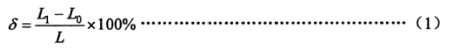
Style:
- δ: fundamental error, %.
- L1: Stroke value of the output shaft (lever) in degrees (°), millimeters (mm) or revolutions (r); L2: Stroke value of the output shaft (lever) in degrees (°), millimeters (mm) or revolutions (r).
- Lo: Theoretical value of the output shaft (rod) travel in degrees (-), millimeters (mm) or revolutions (r).
- L: Rated travel value of the output shaft (rod) at full stroke in degrees (°), millimeters (mm), or revolutions (r).
Verify that the fundamental error of each measurement at each measurement point does not exceed that specified in 6.1.1.
7.4 Basic deviation of the position output signal
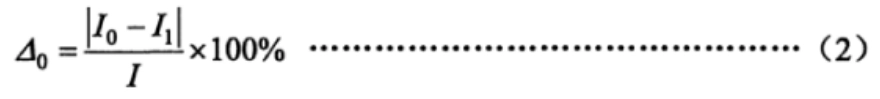
Connect the position output signal of the actuator to an external load impedance of 250 Ω and run it to the "fully closed" position to adjust the position output signal.The actuator should be set to 4mA; run the actuator to the "fully open" position, adjust the position output signal to 20mA, then run the actuator and set the position output signal to 20mA in the positive position,The position output signal value of each point is recorded separately in the direction of reverse travel, and the basic deviation is calculated according to Equation (2).
Style:
- △0: basic deviation of position output signal, %.
- Io: theoretical value of the position output signal in milliamps (mA).
- I1: measured value of the position output signal in milliamps (mA).
- I: Position output signal range in milliamps (mA) (4 mA to 20 mA, I=16 mA; 0 mA to 20 mA, I=20 mA).
Verify that the basic deviation of each measurement at each measurement point does not exceed the provisions of 6.1.2.
7.5 Returns
The actuator backlash is determined by the absolute value of the maximum algebraic difference between the basic errors of the forward and reverse stroke at each test point measured in 7.3 and 7.4.
7.6 Dead zones
The deadband of the modulating actuator shall be measured at points 25%, 50%, and 75% of rated travel.
The measurement procedure is as follows:
Slowly change (increase or decrease) the input signal until there is a perceptible change in travel of the output shaft (rod), recording the input signal value I(mA) at this point.
--Then slowly change (decrease or increase) the input signal in the opposite direction until there is a perceptible change in travel of the output shaft (rod), recording the input signal value I² (mA) at this point.
Calculate the dead zone according to equation (3).
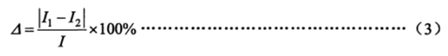
Style:
- △: dead zone, %.
7.7 Time Lag
Apply a step signal of 15% of the input range to the input signal terminal of the regulated actuator, record the input signal curve and the position output signal curve with an oscilloscope, and observe whether the time difference from the starting value of the input signal to the beginning of the change of the output signal exceeds the provisions of 6.1.5.
7.8 Rated travel time error
Apply a rated load of 45% to 55% to the actuator, add a step signal sufficient to move the actuator output shaft (rod) the rated stroke, and record the time the output shaft (rod) moves the rated stroke. Calculate the rated travel time error according to Equation (4):

Style:
- δt: rated travel time error, %.
- t1: Measured time in seconds (s) for the output shaft (rod) to move the rated stroke.
- t: Theoretical value of the rated travel time in seconds (s).
7.9 Starting characteristics
Apply the rated load in the opposite direction on the output shaft (rod) of the actuator and change the supply voltage to the lower limit value, then apply the input signal to observe whether the actuator can start normally.
7.10 Repeatability error of travel control mechanism
For the actuator with stroke control mechanism, apply the rated load of 25%~30% to the output shaft (rod), and make the actuator act alternately in positive and negative strokes for 5 times, and then observe and record the stroke value of the output shaft (rod) during the switching action of the stroke control mechanism. Observe and record the travel value of the output shaft (lever) during the switching action of the stroke control mechanism. Take the average value of the five recorded values as the base value, calculate the error between the recorded value and the base value each time, and determine whether the error obtained from each calculation exceeds the provisions of 6.1.8.
7.11 Insulation resistance
Under the atmospheric conditions of the general test and when the actuator is unloaded, disconnect the power supply of the product under test, put the power switch in the on position, short the input terminals and power supply terminals, and then use an insulation resistance meter with a DC voltage of 500V to measure whether the insulation resistance between the terminals specified in 6.1.9 exceeds the provisions of 6.1.9.
7.12 Dielectric strength
Under the atmospheric conditions of the general test and when the actuator is unloaded, disconnect the power supply of the product under test, make the power switch in the on position, short the input terminal and power terminal respectively, and then slowly increase the test voltage from zero to the specified value according to the voltage and frequency stipulated in 6.1.10 and keep it for 1min, observe whether there is breakdown and flying arc phenomenon, and then slowly decrease the test voltage to zero, and then slowly decrease the test voltage to zero, and then slowly decrease the test voltage to zero. Disconnect the test power supply.
7.13 Temperature rise
Measure the cold-state resistance of the motor and power transformer windings with a bridge before the test, and then measure the hot-state resistance of the motor and power transformer windings immediately after 12h of continuous operation according to method 7.14.
Calculate the temperature rise of the motor winding and the power transformer winding according to equation (5) respectively.

Style:
- Q: Temperature rise in degrees Celsius (℃)
- R₂: winding thermal resistance in ohms (Ω).
- R₁: cold resistance of the winding in ohms (9).
- T1: room temperature in degrees Celsius (℃) for cold resistance measurements.
- T₂: Room temperature in degrees Celsius (℃) at which the thermal resistance is measured.
Alternatively, stick the temperature sensor to the outer surface of the motor in the cold state for 1 min and record its temperature value Tj, and then measure the temperature value T₂ of the temperature sensor with the same sensor immediately after 12h of continuous operation according to the method in 7.14, then the temperature rise Q=T₂-Ti.
Alternatively, use an infrared thermometer to measure the outer surface temperature Ti in the cold state of the motor, and then use the same thermometer to measure the outer surface temperature T₂ in the hot state of the motor immediately after 12h of continuous operation according to 7.14, then the temperature rise Q = T₂-Ti.
7.14 Long-term operational stability
Make the actuator in the rated stroke and apply the rated load of 30%, and run 48h according to the requirements of 4.2.6 with the turn-on continuous rate of 20%~80% and the number of turn-on times per hour, and confirm whether the actuator is in accordance with the requirements of 6.1.12 after the test.
7.15 Maximum and Minimum Control Torque and Thrust Repeatability Errors
The test procedure is as follows:
a) Mount the actuator on the test bench and set the torque protection value to the maximum control torque or the maximum control thrust in the on and off directions, respectively.Start the actuator and load it gradually until the "over-torque" or "over-thrust" alarm is activated and the output torque or thrust is measured.Force value. Measure three times in each direction, open and close, and take the average value as the base value of output torque or thrust.
b) Mount the actuator on the test bench, set the torque protection value to the minimum control torque or the minimum control thrust value in the open and close directions respectively, start the actuator and load it gradually until the alarm action of "over torque" or "over thrust", and measure the output torque or thrust value. Measure the output torque or thrust value. Measure the output torque or thrust value. Measure three times in each of the open and close directions and take the average value as the base value of output torque or thrust.
c) Calculate the repetition error of the control torque or thrust according to equation (6).
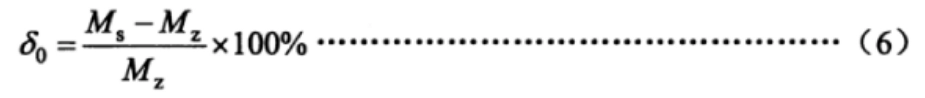
Style:
- δ0: Repeatability error of control torque or thrust, %
- Ms::Measured output torque in Newton meters (N-m), or thrust in Nm.
- Mz: output torque base value in Newton meters (N -m), or thrust base value in Nm.
7.16 Manual-electric switching mechanism
The test procedure is as follows:
a) No-load switching check. Switch the actuator from electric to manual state, turn the handwheel so that the output shaft rotates clockwise and counterclockwise for not less than one revolution; then run the actuator electrically so that the output shaft rotates positively and negatively for not less than one revolution. Repeat twice each to check whether it complies with the provisions of 6.1.14.
b) Load switching check. Mount the actuator on the test bench, adjust the protective torque in the opening and closing directions to the maximum control torque, operate the actuator electrically and load it gradually until the torque switch operates, and then repeat the test of a) without unloading after stopping the actuator to check whether it complies with the provisions of 6.1.14.
7.17 Basic functions of the Smart
7.17.1 Display functions
Through the human-machine interface to check whether the display information of working parameters, operation status information, fault alarms and other display information is normal, and whether the display content is complete and clear.
7.17.2 Parameter setting function
Without opening the cover of the electrical enclosure, perform operations such as setting of operating parameters such as stroke and torque, calibration of current input signals, and adjustment of current output signals through the human-machine interface to confirm whether the parameter setting function is normal.
7.17.3 Field configuration functions
Without opening the electrical cover, set the 4 switching contact outputs of the actuator to open position closed, open position disconnected, close position closed and close position disconnected through the HMI. Start the actuator to the open position and close position and check whether the 4 switching contact outputs meet the setting requirements. For switching contacts whose status does not change after the power supply is turned off, check whether the outputs meet the requirements after disconnecting the power supply.
Set the torque protection value of the actuator to 40% and 100% of its rated torque value respectively, start the actuator and load it gradually until it exceeds the set value, check whether the torque switch is flipped immediately, if the action is normal, repeat the process for three times, and if all of them are able to reverse the action immediately, then they are in compliance with the requirements.
Under no-load condition, set the local control mode of the actuator to "Tap" and "Hold" respectively, and switch the actuator through the knob on the local operation panel of the actuator to confirm whether it works normally.
Set the remote control mode of the actuator (or external connection) to "Tap" and "Hold" respectively, and switch the actuator through external signals according to the manufacturer's requirements to confirm whether it works properly.
7.17.4 Fault self-diagnosis and alarm function
Under no-load condition, energize the actuator, open the electrical cover and disconnect the motor temperature lead wire from the control system of the actuator, and observe whether the actuator shows motor overheating alarm. In addition, put the actuator into the temperature test chamber and adjust the temperature to the temperature point of motor overheating alarm specified by the manufacturer, with a tolerance of ±5℃, and then check whether the temperature switch of the motor operates after a continuous period of 2h. For three-phase power supply actuator, under the condition of energizing, disconnect any line of power supply from the actuator and confirm whether the actuator has alarmed accordingly.
7.17.5 Power supply phase sequence adaptive function
For intelligent actuators using a three-phase power supply, arbitrarily change the phase sequence of the primary power supply to confirm that the actuator is switched in the correct direction both locally and remotely.
7.17.6 Output torque (thrust) continuous measurement function
Place the actuator on the test bench, continuously change the torque (thrust) applied to the actuator during operation, and observe whether the torque (thrust) value displayed on the HMI of the actuator changes continuously.
7.18 Noise
Under the condition that doors and windows of the room are closed and the ambient noise in the room does not exceed 45dB, start the actuator running with no load and repeat the operation two times in each direction of opening and closing. Measure the noise of the actuator at a distance of 1m from the surface of the actuator with a sound level meter and check whether the noise meets the requirements of 6.1.16.
7.19 Stepless (variable frequency) speed control
Set the actuator to reach the target position with reduced speed control, start the actuator with no load to run at the rated speed to a limit position, and measure the change of speed when the actuator is in place with a tachometer.
After adding the rated load of 85% to the actuator, start the actuator to run at one-tenth of the rated speed to check whether the operation in the opening and closing directions is normal and whether the speed error during operation meets the requirements of 6.1.17.
7.20 Ambient temperature effects
The actuator is placed in a temperature test chamber under no-load conditions at the following test temperatures and test sequence:
- - Actuators with operating ambient temperature of -10℃~55℃:
20 °C (reference), 40 °C, 55 °C, 20 °C, 0 °C, -10 °C, 20 °C.
--Actuators with operating ambient temperature of -20℃~60℃:
20 °C (reference), 40 °C, 60 °C, 20 °C, 0 °C, -20 °C, 20 °C.
--Actuators with operating ambient temperature of -30℃~70℃:
20°C (reference), 45°C, 70°C, 20°C, 0°C, -30°C, 20°C.
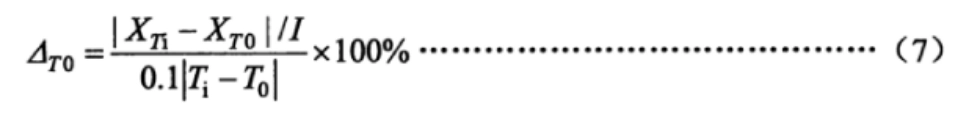
If agreed by the parties concerned, the test may be conducted at four temperatures only: 20℃ (reference), maximum temperature, minimum temperature, and 20℃. The tolerance of each temperature point is ± 2 ℃, in each temperature point should be maintained for 2 h, so that the product internal thermal stability, in the full stroke of the 0%, 100% two positions, respectively, to measure the proportional control and position of the signal output of the low-end value and the high-end value. Take the average of three measurements at each temperature point, according to formula (7) and formula (8) to calculate when each of the two neighboring temperatures every change of 10 ℃, the output of the low-end value and the amount of change in the value of the high end, and to confirm that the results are consistent with the requirements of 6.2.1.
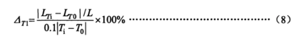
Style:
- △T0: the amount of change in the low and high end values of the position output signal for every 10℃ change in temperature, %.
- XTi: the low and high end of the measured position output signal at adjacent temperatures, in milliamps (mA).
- XT0: the low and high end of the measured position output signal at the starting temperature in milliamps (mA); XT0: the low and high end of the measured position output signal at the starting temperature in milliamps (mA).
- Ti: adjacent temperature in degrees Celsius (°C).
- T0: Starting temperature in degrees Celsius (°C).
- △T1: the amount of change in the low and high end values of the output shaft (rod) for every 10℃ change in temperature, %;
- LTi: low and high travel values of the output shaft (rod) measured at adjacent temperatures, in degrees (°), millimeters (mm), revolutions (r).
- LT0: Measured low and high travel values of the output shaft (lever) at the starting temperature in degrees (°), millimeters (mm), revolutions (r).
7.21 Effects of heat and humidity
Under no-load condition, the actuator was put into the hot and humid test chamber, and the temperature was firstly increased to 40℃±2℃, and then the relative humidity was adjusted to 91%~95% and kept for 48 h. The actuator was then put into the hot and humid test chamber.
Immediately after the damp heat test the actuator is removed from the damp heat box and the insulation resistance between the terminals as specified in 6.2.2 is measured according to 7.11.
7.22 Power supply voltage effects
Under no-load condition, adjust the power supply voltage of the actuator from the nominal value to the upper and lower limit values respectively, and measure the low end and high end values of the proportional control and position signal outputs at the two positions of 0% and 100% of the full-stroke, respectively.
Take the average value of three measurements on each measurement point, calculate the change of lower limit value and range according to formula (9) and formula (10), and confirm thatWhether the results comply with the requirements of 6.2.3.
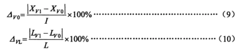
Style:
- △V0: the amount of change in the low and high end values of the position output signal when the power supply voltage changes, %.
- XV1: Low and high end of measured position output signal at upper and lower limit voltages, in milliamps (mA).
- XV0: the low and high end of the measured position output signal at nominal voltage, in milliamps (mA).
- △VL: the amount of change in the low and high end values of the output shaft (rod) when the supply voltage changes, %.
- LV1: Low and high end travel values of the output shaft (lever) measured at upper and lower limit voltages in degrees (°), millimeters (mm), revolutions (r).
- LV0: Low and high end travel values of the output shaft (rod) measured at nominal voltage, in degrees (°), millimeters (mm), revolutions (r).
7.23 Mechanical vibration effects
Under no-load condition, install the actuator on the vibration test bench and run the actuator to the full-stroke 0% and 100% respectively, and sweep the vibration in three mutually perpendicular directions at the frequency of 10Hz to 150Hz to find the resonance point, and then carry out the vibration test at the resonance frequency for 30 min respectively, and carry out the vibration test at the frequency of 150Hz if there is no resonance point. If there is no resonance point, the vibration test is conducted at 150 Hz for 30 min.
Measure the low end and high end values of the actuator output during the test, calculate the changes of the low end and high end values according to Equation (11) and Equation (12), and check whether the result meets the requirements of 6.2.4.
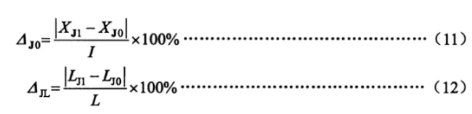
Style:
- △J0:The amount of change in the low and high end values of the position output signal during mechanical vibration, %.
- XJ1: The low and high end of the position output signal measured during the vibration test, in milliamps (mA).
- XJ0::The low and high end of the position output signal in milliamps (mA) measured before the vibration test.
- △ JL: the amount of change in the low and high end values of the output shaft (rod) during mechanical vibration, %.
- LJ1: low and high end travel values of the output shaft (rod) measured during the vibration test, in degrees (°), millimeters (mm), revolutions (r).
- LJ0: the low and high end travel values of the output shaft (rod) measured before the vibration test, in degrees (°), millimeters (mm), revolutions (r).
7.24 Environmental impacts of transportation
Conduct temperature, impact and free fall tests according to the test parameters specified in 6.2.5 of this standard and the methods in GB/T 25480. After the test, it is allowed to adjust the zero position, and then carry out performance test and appearance inspection respectively.
NOTE: The high temperature test is exempted when the ambient temperature impact test has been conducted at 55°C (or above).
7.25 Radiofrequency electromagnetic field radiation immunity
Under no-load condition, run the actuator to the full-stroke position 50%, according to the requirements of GB/T17626.3, use the radiation electromagnetic field with the frequency in the range of 80 MHz to 1000 MHz and the intensity of 3V/m to radiate the actuator at a distance of 3 m from the actuator, and at this time, observe and record the change of the output signal of the position feedback or the value of the output shaft (rod) stroke. At this time, observe and record the change of position feedback output signal or output shaft (lever) travel value to confirm whether the value meets the requirements of 6.2.6 in this standard.
7.26 Electrical fast transient pulse group immunity
Under no-load condition, run the actuator to the position of 50% with full stroke, and then according to the requirements of GB/T 17626.4, apply plus or minus 1000V at the power supply terminal and plus or minus 500V at the signal input terminal, and at this time, observe and record the changes of the position feedback output signal or the output shaft (rod) stroke value to confirm whether the value meets the requirements of 6.2.7 in this standard. Check whether the value meets the requirements of 6.2.7 of this standard.
7.27 Surge (Impact) Immunity
Under no-load condition, run the actuator to the position of 50% with full stroke, and apply a voltage of plus or minus 1kV between the power supply line of the actuator and the ground according to the requirements of GB/T 17626.5. At this time, observe and record the changes of the position feedback output signal or the output shaft (rod) stroke value to confirm whether the value meets the requirements of 6.2.8 in this standard.
7.28 Electrostatic discharge immunity
Under no-load condition, run the actuator to the full-stroke position 50%, ground the outer casing of the actuator reliably according to the requirements of GB/T 17626.2, apply positive and negative 4kV contact discharge to the actuator, and then apply positive and negative 8kV air discharge, at this time, observe and record the change of the output signal of the position feedback or the value of the output shaft (rod) travel to confirm whether the value complies with 6.2.9 of this standard. 6.2.9 of the requirements.
7.29 Industrial frequency magnetic field immunity
Under no-load condition, put the actuator on the external magnetic field test frame, run the actuator to the position of 50% at full stroke, with the magnetic field strength of 400 A/m, and the test direction of X/Y/Z, and conduct the test according to the requirements of GB/T17626.8. At this time, observe and record the position feedback output signal or the change of output shaft (rod) travel value to confirm whether the value meets the requirements of 6.2.10 of this standard.
7.30 Exterior
Check whether the external surface is flat and smooth by visual inspection and hand feeling, and whether there are cracks, burrs, bumps and other defects affecting the quality of appearance, and whether the surface coating is firmly adhered, flat, smooth, uniform in color and lustre, and whether it is free from oil stains, indentation and other mechanical damages. The display screen of the actuator with display function is clear visually and there are no missing characters.
7.31 Enclosure protection class
Carry out IP67 or IP65 shell protection test according to the method stipulated in GB 4208-2008.
7.32 Explosion protection
According to the provisions of GB 3836.1 and GB3836.2, send it to the state-recognized testing unit for testing.
8 Inspection rules
8.1 Factory inspection
Each actuator shall be inspected and qualified by the quality inspection department of the manufacturer and the product certificate shall be issued by the inspection department before leaving the factory. The factory inspection items are specified in Table 3.
8.2 Type examination
Type inspection shall be carried out when one of the following conditions exists:
-Finalization of new trial products;
--Normal production of products with significant changes in structure, materials, and processes that may affect product performance;
-Requirements for type testing by the relevant State authorities;
Product discontinued for more than one year;
--Products have been in continuous production for more than three years.
Type inspection items in accordance with the provisions of Table 3 of this standard.
Type test, the sampling method should be consistent with GB/T 18271.1-2000 in the provisions of 6.7.
| 表3 检验项目 | |||||||
|---|---|---|---|---|---|---|---|
| 序号 | 项 目 | 出厂检验 | 型式检验 | ||||
| regulating type | switching type | regulating type | switching type | 技术要求 | 试验方法 | ||
| 1 | 基本误差 | △ | △ | △ | 6.1.1 | 7.3 | |
| 2 | 位置输出信号基本偏差 | △ | △ | △ | △ | 6.1.2 | 7.4 |
| 3 | 回差 | △ | △ | △ | △ | 6.1.3 | 7.5 |
| 4 | 死区 | △ | — | △ | — | 6.1.4 | 7.6 |
| 5 | 时滞 | — | — | △ | — | 6.1.5 | 7.7 |
| 6 | 额定行程时间误差 | △ | △ | △ | △ | 6.1.6 | 7.8 |
| 7 | 起动特性 | — | — | △ | △ | 6.1.7 | 7.9 |
| 8 | 行程控制机构重复性误差 | — | — | △ | △ | 6.1.8 | 7.1 |
| 9 | 绝缘电阻 | △ | △ | △ | △ | 6.1.9 | 7.11 |
| 10 | 绝缘强度 | △ | △ | △ | △ | 6.1.10 | 7.12 |
| 11 | 温升 | — | △ | △ | 6.1.11 | 7.13 | |
| 12 | 长期运行稳定性 | — | — | △ | △ | 6.1.12 | 7.14 |
| 13 | 最大与最小控制转矩和推力重复性误差 | △ | △ | △ | △ | 6.1.13 | 7.15 |
| 14 | 手动-电动切换机构 | △ | △ | △ | △ | 6.1.14 | 7.16 |
| 15 | 智能型的基本功能 | * | * | * | * | 6.1.15 | 7.17 |
| 16 | 噪声 | — | △ | △ | 6.1.16 | 7.18 | |
| 17 | 无级(变频)调速 | △ | △ | △ | △ | 6.1.17 | 7.19 |
| 18 | 环境温度影响 | — | △ | △ | 6.2.1 | 7.2 | |
| 19 | 湿热影响 | △ | △ | 6.2.2 | 7.21 | ||
| 20 | 电源电压影响 | △ | △ | 6.2.3 | 7.22 | ||
| 21 | 机械振动影响 | △ | △ | 6.2.4 | 7.23 | ||
| 22 | 运输环境影响 | △ | △ | 6.2.5 | 7.24 | ||
| 23 | 射频电磁场辐射抗扰度 | * | * | 6.2.6 | 7.25 | ||
| 24 | 电快速瞬变脉冲群抗扰度 | * | * | 6.2.7 | 7.26 | ||
| 25 | 浪涌(冲击)抗扰度 | * | * | 6.2.8 | 7.27 | ||
| 26 | 静电放电抗扰度 | — | — | * | * | 6.2.9 | 7.28 |
| 27 | 工频磁场抗扰度 | — | * | * | 6.2.10 | 7.29 | |
| 28 | 外观 | △ | △ | △ | △ | 6.3 | 7.3 |
| 29 | 外壳防护等级 | — | — | △ | △ | 6.4 | 7.31 |
| 30 | 防爆性能 | — | △ | △ | 6.5 | 7.32 | |
| 注:“△”表示应检项目,“一 ”表示不检项目,“*”表示仅适用于智能型执行机构。 | |||||||
9 Marking, packaging and storage
9.1 Logo
9.1.1 A nameplate shall be provided in a conspicuous place on the actuator and shall be indicated on the nameplate:
--Manufacturer's name and trademark;
--Product name and model number;
-The main technical parameters of the product;
--The temperature of the environment in which it is used;
--Protection level;
--Use of power supply conditions (voltage, current and frequency).
--Manufacturing year and month;
--Manufacturing number.
9.1.2 Explosion-proof actuators shall be marked on the nameplate in addition to those specified in 9.1.1:
--Explosion-proof marking in accordance with national regulations is marked on the upper right of the nameplate;
--Explosion protection class;
-Explosion protection certificate number.
9.2 Packaging
9.2.1 Packaging
The products should be packed according to the requirements of GB/T13384. The packing box should be accompanied by product certification, relevant technical documents and packing list.
9.2.2 Packing List
The packing list shall include the following and shall be stamped with the seal of the factory inspector:
--Manufacturer's name and address;
--Product name and model number;
-- Name and number of documents attached;
--Product conformity certificate;
--Carton quantity;
--Carton date.
9.2.3 Packaging symbols
The outer surface of the packing box should have a marking that cannot be easily erased, the contents of which are:
--Manufacturer's name;
--Product name, model number;
Words or symbols such as "up" and "down";
--Gross weight and external dimensions (L x W x H).
9.3 Storage
The product should be stored in a ventilated room or storage environment specified by the manufacturer at a temperature of -10℃~45℃ and a relative humidity of not more than 85%, and the surrounding air should not contain hazardous substances that play a corrosive role in the product.
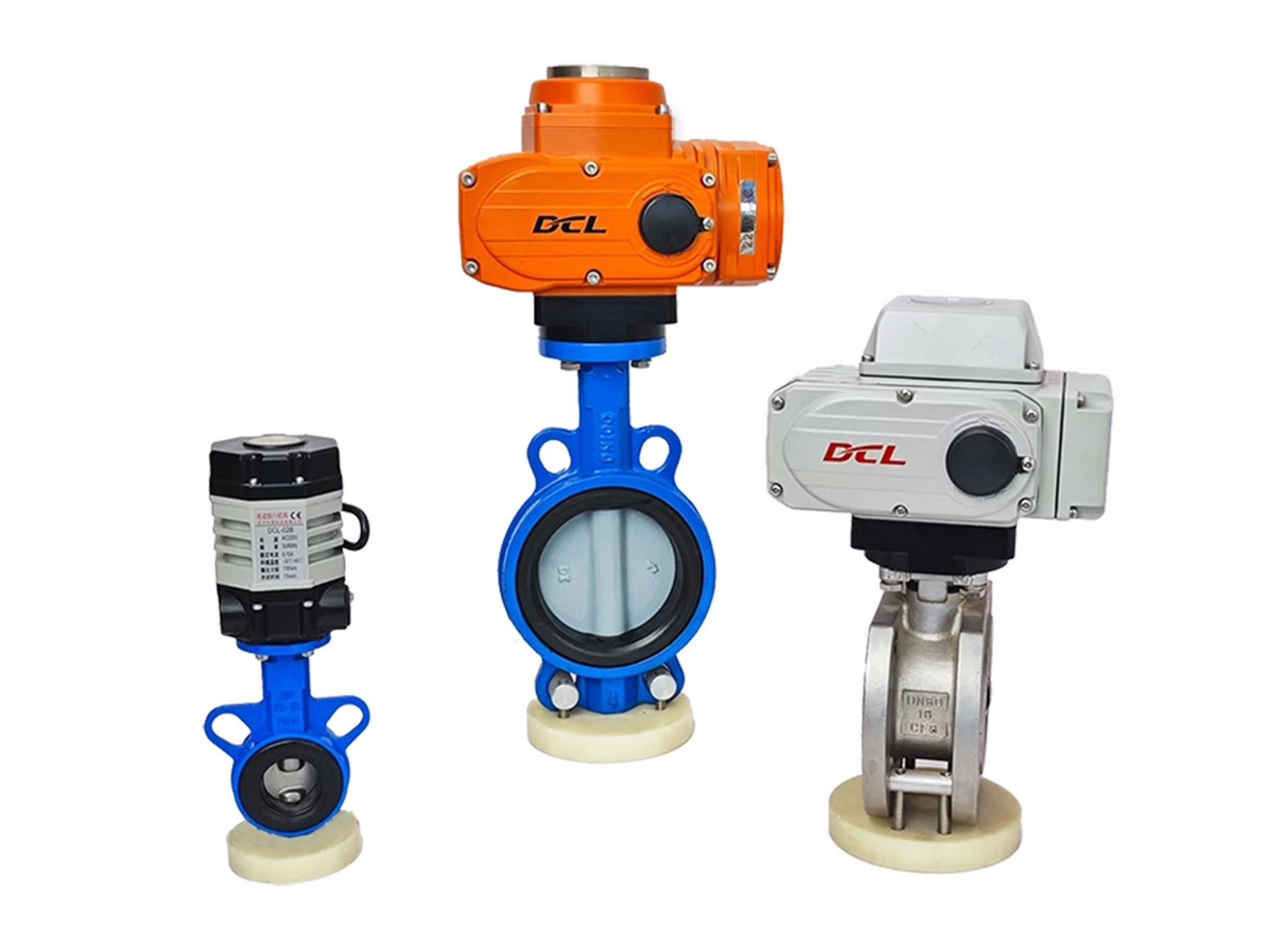
Selection of DCL electric actuator

Torque: 20-600Nm
Time: 4S~60S
Angle: 0~90° | 0~360°

Torque: 20-2500Nm
Time: 4S~75S
Angle: 0~90° | 0~360°
Torque: 12-1200Nm
Time: 2S~12S
Angle: 0~90° | 0~360°

Torque: 9-18Nm
Time: 7S~60S
Angle: 0~270°


 Egong.com.cn 42018502006527 No.