


DCL Actuator Modbus Module Application Manual
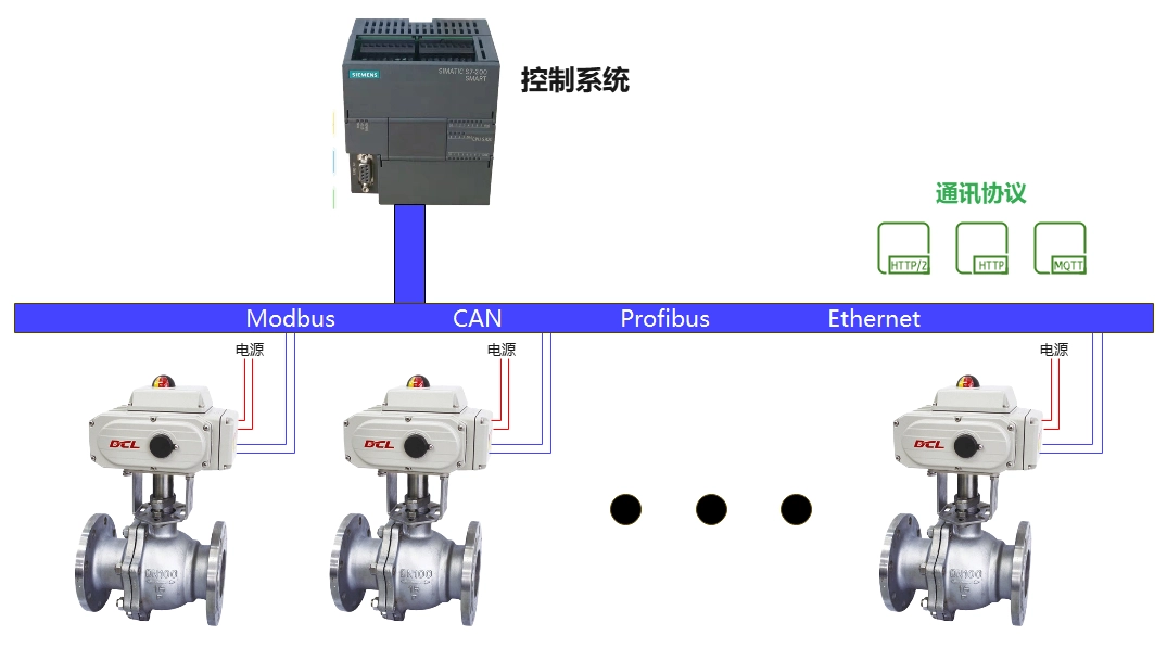
DCL series actuators support Modbus-RTU protocol. Referring to this application manual, you can connect DCL actuators to Modbus.
Panel Description
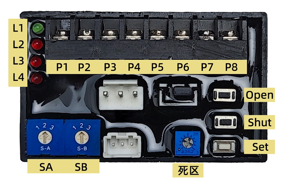
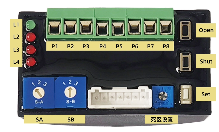
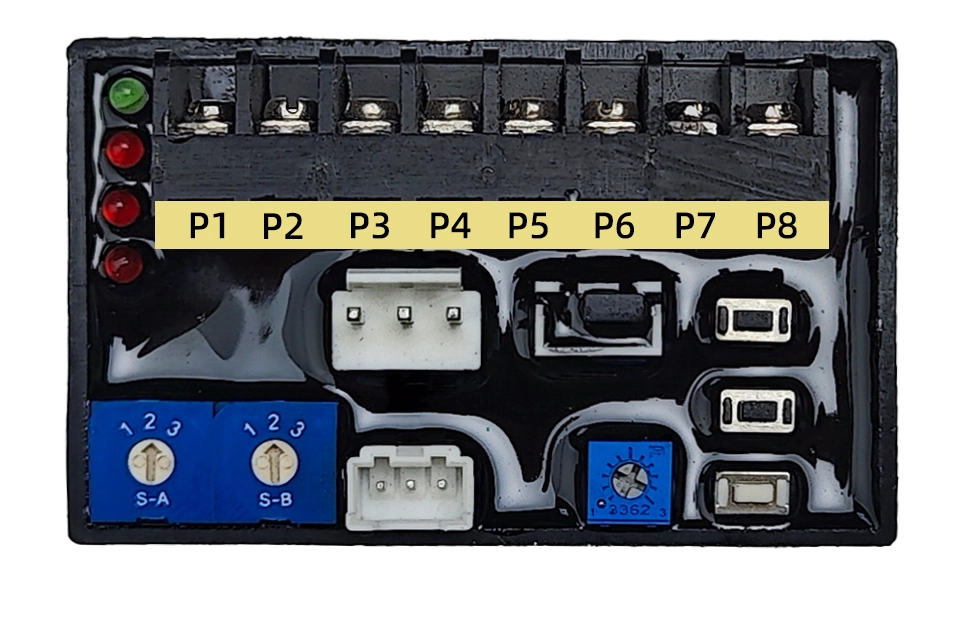
1. Interface definition
P1: 220VAC N line
P2: 220VAC L line
P3: 4-20mA input-
P4: 4-20mA input +
P5: 4-20mA output-
P6: 4-20 mA output +
P7: RS485 A
P8: RS485 B
2. Key
Open: In the "setting state" (i.e. the arrow of the selector switch SA is pointing to "2") press this key to operate the actuator in the open position, release this key to stop the motor, press Set and Open at the same time to calibrate the fully open position.
Shut: Press this key in the "setting state" to operate the actuator in OFF position, release this key to stop the motor, press Set and Shut at the same time to calibrate the full OFF position.
Set: Realize specific functions by working with Open and Shut in the "Setting State".
3、Selector switch
SA: Select the input signal positive and negative mode and setting status, the positive and negative setting must be set in the power-on state to be effective, and the arrow direction corresponds to the function as follows (set to 1 at the factory).
1-Positive action 2-Setting status 3-Reverse action
SB: Setting the safe position, according to which the actuator operates to a specific position in case of loss of external analog control signal (factory setting 2).
1-Operate to fully open position 2-Hold current position 3-Operate to fully closed position
Note: When modbus control mode is used, SB should be kept at 2 speeds.
4、Deadband value setting potentiometer
Used to set the deadband value. Potentiometer opening from 1-10, corresponding to the deadband value 0.5%-5.0% (factory deadband value is set to 1.5%).
5. Indicator light
L1: Green, power indication, the light is on when power is connected between N and L of the servo controller power supply terminal;
L2: Red, Input Signal Failure Fault Indication, Lights up when the input signal fails;
L3: Red, position detection circuit fault indication, open potentiometer leads open, shorted, or damaged itself when the light is on;
L4: Red: Jamming fault indication, light comes on when jamming occurs.
set up
If the arrow of selector switch SA points to position "2″, it enters the setting state. In the setting state, it is possible to carry out travel calibration, selection of input signal failure processing method, deadband value setting, manual operation and output current correction.
1、Stroke calibration
All-off position calibration: Adjust the valve to the fully closed position by pressing the Open and/or Shut buttons, first press the Set button without letting go, then press the Shut button, keep both buttons pressed at the same time for about 4S clocks, when the indicator L2 is on, release the Shut and Set buttons at the same time, L2 goes off, and the calibration of the fully closed position is completed.
Full open position calibration: Adjust the valve to the fully open position by pressing the Open and/or Shut buttons, first press the Set without releasing, then press the Open button, keep both buttons pressed at the same time for about 4S clocks, when the indicator light L2 is on, release the Open and Set buttons at the same time, L2 goes off, and the calibration of the fully open position is completed.
2、Set Modbus address
The communication address and baud rate can be modified by modbus communication commands, and the factory address of the actuator is 1, and the baud rate is 9600 (refer to the example of communication commands).
3、Deadband value setting
The deadband setting potentiometer turns clockwise to increase the deadband value, and counterclockwise to decrease the deadband value. There is a scale on the front side of the potentiometer, and every time the potentiometer is rotated by one degree, the deadband value changes by 0.5%. When the deadband value is set to less than 0.5%, the servo controller will process it according to 0.5%.
The valve can be opened and closed manually by pressing Open or Shut in the setting state.
(of a computer) run
Set the selector switch SA to position "1" or "3" to enter automatic operation.
- After power-on, the actuator defaults to follow the 4-20mA input signal for opening adjustment.
- Sending commands via Modbus enables the actuator to work in communication control mode and automatically return to analog control mode after the actuator is powered off and restarted.
Note: When communication control is used, it should be ensured that the SB is 2-steps, and the control mode and opening value should be written for each control command to prevent inactivity caused by restarting or running to a safe position.
Control of actuator opening using 4-20mA
| 输入信号 | 4mA | 8mA | 12mA | 16mA | 20mA |
| 指针位置 | CLOSE(0) | 2.5 | 5 | 7.5 | OPEN(0) |
| 阀门开度 | 0% | 25% | 50% | 75% | 100% |
| output signal | 4mA | 8mA | 12mA | 16mA | 20mA |
Notes:
- Reaction, the input current is 4mA corresponds to the opening degree of the valve position is 100%, at this time the output current is 20mA; input current is 20mA corresponds to the opening degree of the valve position is 0%, at this time the output current is 4mA.
- Servo controller accuracy level 1, the basic error does not exceed ± 1%, back less than 1%
Actuator opening control using Modbus
physical layer
DCL actuators support the Modbus-RTU protocol and use the RS485 interface at the physical layer.
Communication address: configurable from 1 to 127, default is 1
Communication baud rate: configurable, default is 115200
Serial format: 1 start bit + 8 data bits + 1 stop bit
Supports broadcasting function
1、Modbus interface

P1: Power-
P2: Power +
P7: RS485 A
P8: RS485 B
P3~P6: analog reserved signal (4~20mA/0~10V)
2. Modbus wiring schematic:
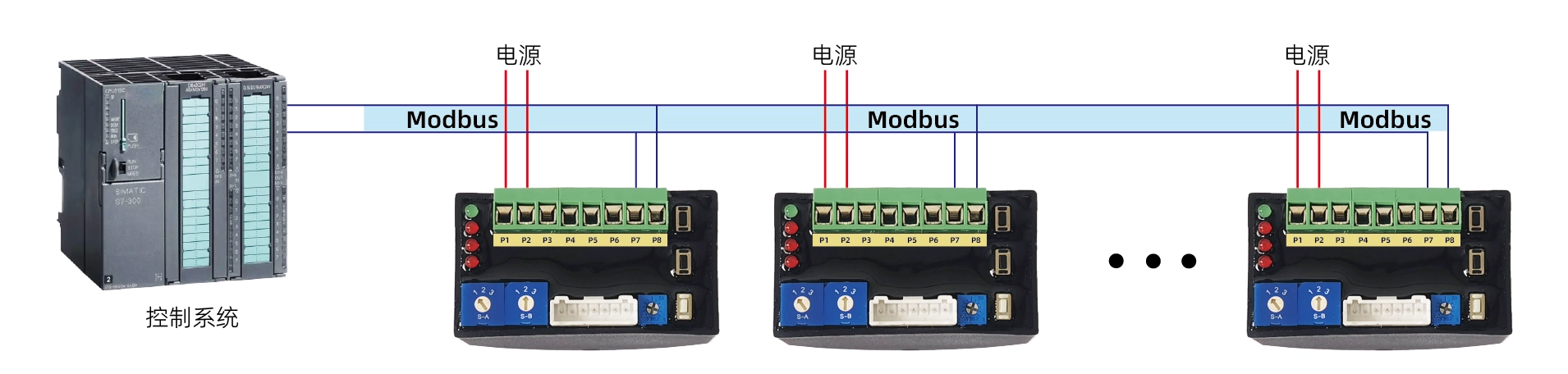
application layer (computing)
1. ADU
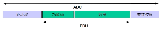
2、Function Code
| ID | 名称 | 描述 |
|---|---|---|
| 0x03 | 读多个寄存器 | 在一个远程设备中,使用该功能码读取保持寄存器连续块的内容 |
| 0x06 | 写单个寄存器 | 在一个远程设备中,使用该功能码写单个寄存器 |
| 0x10 | 写多个寄存器 | 在一个远程设备中,使用该功能码写连续寄存器块(1 至约 120 个寄存器) |
3、Setting communication parameters
- Registers 0x0040-0x0042 are used to configure communication parameters
- First, write 0xA501 to register 0x0040 to enter configuration mode, then modify registers 0x0041 and 0x0042 to change the communication address and baud rate, respectively.
- After the modification is completed, the parameters will be updated within 1 second, and subsequent communications must follow the new parameters
- Configuration mode should be exited when modifications are complete (i.e., write 0x0000 to register 0x0040)
4. Forcing into the default communication mode
- When SA is in 2nd gear and SB is in 2nd gear, long press the KS button for about 3 seconds, wait for the red light to flash, then release the KS button, then long press the KC button for about 3 seconds, wait for the red light to light up, then release the KC button, at this time, the communication parameter is forced to be the default state, and the communication parameter will keep the default value when the SA is adjusted to be the 1st gear to exit the current state. After restarting the device, the actuator will operate according to the communication parameters set before.
- When you forget the previous communication parameters, you can use this method to enter the default communication state and communicate to configure the communication parameters.
5. Register List
| 寄存器地址 | 寄存器位 | 信号组 | 信号名 | 最小值 | 最大值 | 单位 | 读/写 | 类型 | 真值表 | 描述 |
|---|---|---|---|---|---|---|---|---|---|---|
| 0x0010 | b15-b5 | \ | \ | \ | \ | \ | r/w | hex | 保留0 | 保留 |
| b5 | \ | \ | \ | \ | \ | r/w | hex | 保留0 | 保留 | |
| b4 | control | stop | \ | \ | \ | r/w | hex | 1:停止, 0:正常 | stop running | |
| b3 | \ | \ | \ | \ | \ | r | hex | 保留0 | 保留 | |
| b2 | \ | \ | \ | \ | \ | r | hex | 保留0 | 保留 | |
| b1-b0 | control | mode | \ | \ | \ | r/w | hex | 1: 通讯控制 其他: 退出通讯控制 | 控制模式 | |
| 0x0011 | b15-b0 | control | SetOpenDegree | 0 | 10000 | % | r/w | int/hex | 0-10000对应 0-100%开度 | 控制阀门的开度(比率系数1/100) |
| 0x0012 | b15-b0 | \ | \ | \ | \ | \ | r | hex | 保留0 | 保留 |
| 0x0013 | b15-b0 | \ | \ | \ | \ | \ | r | hex | 保留0 | 保留 |
| 0x0014 | b15-b0 | \ | \ | \ | \ | \ | r | hex | 保留0 | 保留 |
| 0x0015 | b15-b0 | \ | \ | \ | \ | \ | r | hex | 保留0 | 保留 |
| 0x0016 | b15-b0 | \ | \ | \ | \ | \ | r | hex | 保留0 | 保留 |
| 0x0017 | b15-b0 | \ | \ | \ | \ | \ | r | hex | 保留0 | 保留 |
| 0x0018 | b15-b6 | \ | \ | \ | \ | \ | r | hex | 保留0 | 保留 |
| b5 | infor | errPosition | \ | \ | \ | r | hex | 1: 位置信号故障 | 位置信号故障标志 | |
| b4 | infor | errSignal | \ | \ | \ | r | hex | 1: 输入信号故障 | 输入信号故障标志 | |
| b3 | infor | overTorqueFlag | \ | \ | \ | r | hex | 1: 过载 | 过载标志 | |
| b2 | infor | stuckFlag | \ | \ | \ | r | hex | 1: 堵转 | 堵转标志 | |
| b1 | infor | openRunFlag | \ | \ | \ | r | hex | 1: 关阀中 | 开阀标志 | |
| b0 | infor | closeRunFlag | \ | \ | \ | r | hex | 1: 开阀中 | 关阀标志 | |
| 0x0019 | b15-b0 | infor | openDegree | 0 | 10000 | % | r | int/hex | 0-10000对应 0-100%开度 | 当前阀门的开度(比率系数1/100) |
| 0x001A | b15-b0 | \ | \ | \ | \ | \ | r | hex | 保留0 | 保留 |
| 0x001B | b15-b0 | \ | \ | \ | \ | \ | r | hex | 保留0 | 保留 |
| 0x001C | b15-b0 | \ | \ | \ | \ | \ | r | hex | 保留0 | 保留 |
| 0x001D | b15-b0 | \ | \ | \ | \ | \ | r | hex | 保留0 | 保留 |
| 0x001E | b15-b0 | \ | \ | \ | \ | \ | r | hex | 保留0 | 保留 |
| 0x001F | b15-b0 | \ | \ | \ | \ | \ | r | hex | 保留0 | 保留 |
| 0x0040 | b15-b0 | config | cfgMode | 1 | 127 | \ | rw | hex | 0x0000: 进入常规模式 0xA501: 进入配置模式 | 模式选择,在配置模式下才能修改配置参数 |
| 0x0041 | b15-b0 | config | cmm_addr | 1 | 127 | \ | rw | hex | 1~127 | 设置通讯地址 |
| 0x0042 | b15-b0 | config | cmm_baudrate | \ | \ | \ | rw | hex | 0: 波特率4800 1: 波特率9600 2: 波特率19200 3: 波特率115200 | 设置波特率 写入时按真值表写波特率 读取时按真值表返回 |
| 0x0043 | b15-b0 | \ | \ | \ | \ | \ | r | hex | 保留0 | 保留 |
| 0x0044 | b15-b0 | \ | \ | \ | \ | \ | r | hex | 保留0 | 保留 |
| 0x0045 | b15-b0 | \ | \ | \ | \ | \ | r | hex | 保留0 | 保留 |
| 0x0046 | b15-b0 | \ | \ | \ | \ | \ | r | hex | 保留0 | 保留 |
| 0x0047 | b15-b0 | \ | \ | \ | \ | \ | r | hex | 保留0 | 保留 |
| 0x0048 | b15-b0 | \ | \ | \ | \ | \ | r | hex | 保留0 | 保留 |
Examples of communication commands
1、Control valve position
- Enter the communication control mode:
Send → ◇01 10 00 10 00 01 02 00 01 65 00
Receive ◆01 10 00 10 00 00 01 00 0C - Set valve position: 0%
Send → ◇01 10 00 11 00 01 02 00 00 A5 11
Receive ◆01 10 00 11 00 01 51 CC - Set valve position: 50% (5000 -> 0x1388)
Send → ◇01 10 00 11 00 01 02 13 88 A8 47
Receive ◆01 10 00 11 00 01 51 CC - Set valve position: 100% (10000 -> 0x2710)
Issued: ◇01 10 00 11 00 01 02 27 10 BF 2D
Receive ◆01 10 00 11 00 01 51 CC - stop running
Hair → ◇01 10 00 10 00 01 02 00 11 64 CC
Receive ◆01 10 00 10 00 00 01 00 0C
2、Read the valve status
- Send → ◇01 03 00 18 00 00 02 44 0C
- Receive ◆ 01 03 04 00 30 00 00 FA 3C
3. Setting up a mailing address
- Entering Configuration Mode
Send → ◇01 10 00 40 00 01 02 A5 01 12 00
Receive ◆01 10 00 40 00 00 01 00 1D - Amend the mailing address to read: 2
Hair → ◇01 10 00 41 00 01 02 00 02 28 80
Receive ◆01 10 00 41 00 01 51 DD - Exiting Configuration Mode
Send → ◇02 10 00 40 00 01 02 A5 00 C7 30
Receive ◆02 10 00 40 00 00 01 00 2E
4、Set the communication baud rate
- Entering Configuration Mode
Send → ◇01 10 00 40 00 01 02 A5 01 12 00
Receive ◆01 10 00 40 00 00 01 00 1D - Modify the communication baud rate to 9600
Hair → ◇01 10 00 42 00 01 02 00 01 68 B2
Receive ◆01 10 00 42 00 01 A1 DD - Exiting Configuration Mode
Send → ◇01 10 00 40 00 01 02 A5 00 D3 C0
Receive ◆01 10 00 40 00 00 01 00 1D


 Egong.com.cn 42018502006527 No.