

1. Adjustment Micro-adjustable electrical limits

- Full shut-off position adjustment: first drive the valve to the full shut-off position with the handle, loosen the scale plate locking screw, adjust the scale plate so that the pointer points to the scale line 0 (SHUT to), and tighten the scale plate locking screw. Then use a 2mm hexagonal wrench to adjust the shut-off adjusting shaft S in clockwise direction, and bring the travel stopper D1 to rotate clockwise to trigger the action of K2 and K1 in turn and make a sound, and stop adjusting the shut-off adjusting shaft S when K1 is in action and making a sound.
- Adjustment of fully open position: first gallop the valve to the fully open position with the handle so that the pointer points to the scale line 0 (OPEN direction), then use the 2mm hexagonal wrench to adjust the open position adjustment axis in the counterclockwise direction. Then use the 2mm hexagonal wrench to adjust the open position adjusting shaft in counterclockwise direction, and then drive the travel stopper D2 to rotate counterclockwise to trigger K4 and K3 to act and sound in turn, and then stop adjusting the open position adjusting shaft 0 when K3 is acting and sounding.
2、Adjustment Intermediate position model electrical limits
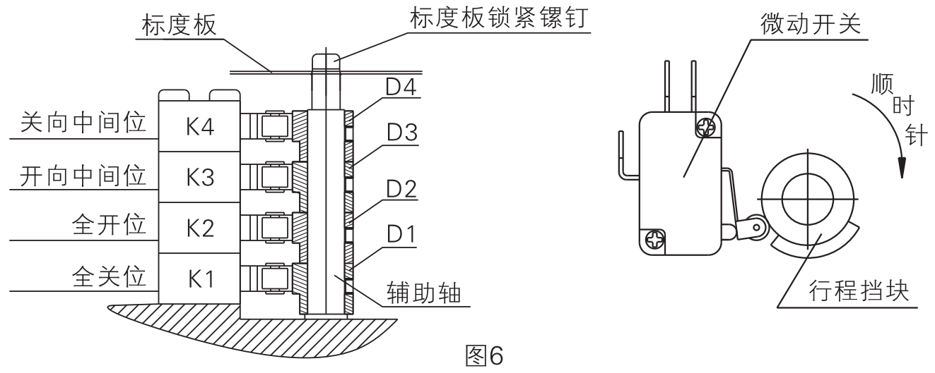
- D1 Adjustment: Drive the valve to the fully closed position with the handle, loosen the scale plate locking screw, adjust the scale plate so that the pointer points to scale 0 (SHUT to), and tighten the scale plate locking screw. Loosen the fixing screw on the travel stopper D1, turn D1 clockwise so that it and the corresponding microswitch K1 just make an action sound, stop turning D1 and lock the screw of D1 to fix the travel stopper D1.
- D2 adjustment: drive the valve to the fully open position with the handle again, make the pointer point to the scale 0 (OPEN to), loosen the fixing screw on the travel stopper D2, turn D2 counterclockwise so that it and the corresponding microswitch K2 just make an action sound, stop turning D2 and tighten the screw of D2 to fix the travel stopper D2.
- D3 adjustment: drive the valve with the handle to the fully open position, then use the handle to drive the valve clockwise to close to run 2. Then loosen the travel block D3 on the fixed screw, counterclockwise rotation D3, and make K3 action sound, and then lock D3.
- D4 adjustment: After driving the valve to the fully closed position with the handle, then use the handle to operate the valve counterclockwise to the open direction for 2 seconds, then loosen the set screw on the travel stopper D4, turn D4 clockwise, and make the K4 action sound, and then lock D4.
Special Tip:
- If the fully closed and fully open positions of the valve and the fully closed and fully open positions of the electric actuator do not match after the valve is installed by the user and need to be adjusted, it can be done as described in 1 or 2 above.
- During factory commissioning, the "closed to center" microswitch is 2° ahead of the "fully closed" microswitch, and the "open to center" microswitch is 2° ahead of the "fully open" microswitch. The "open to center" microswitch is 2° ahead of the "fully open" microswitch, which can be adjusted according to the control requirements in practice. The intermediate microswitch outputs a passive contact signal when it is actuated, and the fully closed and fully open microswitches actuate to control the fully closed and fully open positions of the valve. models A, C, E, and F do not have intermediate microswitches or travel stops.
3. Adjustment of the potentiometer (for C and D models)
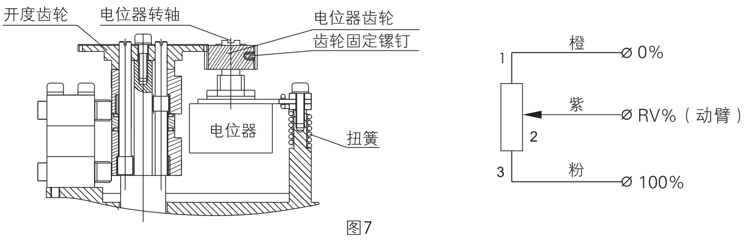
- Use the handle to drive the actuator toward the center position so that the pointer is pointing at the 50% scale.
- Engage the potentiometer gear and the opening gear (gear set screws face outward for easy locking).
- As in Figure 7, use a multimeter to measure the resistance of the potentiometer at the beginning and end (resistance between potentiometer pins 1 and 3), and note down the resistance R.
- Connect the two pens of the multimeter to the potentiometer movable arm (potentiometer pin 2) and to either end of the potentiometer, turn the potentiometer shaft slowly with a flat screwdriver, observe the multimeter reading, and stop adjusting the potentiometer shaft and tighten the gear set screws when the resistance value is R/2 土 2Q.
Special Tip:
- Adjustable type (E-type machine) without microswitch and travel stopper; it is prohibited to mobilize the potentiometer and gear during adjustment.
4. Adjustment Mechanical Limit Block

- Drive the valve to the fully closed position with the handle and actuate the fully closed position limit switch (K1) (the limit switch will make a "click" sound when it is actuated).
- Loosen the lock nut on the right side, use an allen wrench to turn the off limit adjusting screw clockwise and bring the adjusting screw just against the mechanical limit stop, then turn the adjusting screw back half a turn counterclockwise so that the mechanical limit lags the electrical limit by an angular distance of about 2.5° at the full off position, locking the lock nut.
- Perform the adjustment of the left side full open position mechanical limit in the same way.
Special Tip:
- After commissioning, the electrical and mechanical limit positions of the actuator must meet the requirements of Fig. 9. If the mechanical limit positions exceed or overlap the electrical limit positions, the actuator motor will be blocked, heat will be generated and the motor may be burnt.
5、 Electric test run
- Correctly connect the wiring according to the control circuit diagram pasted inside the cover of the system, and turn on the power after confirming that there is no error.
- The actuator drives the valve in the closing direction (clockwise) until the fully closed microswitch K1 is activated and the electric actuator stops.
- The actuator drives the valve in the fully open direction (counterclockwise) until the fully open position microswitch K 3 is activated (K 3 in Fig. 5, K 2 in Fig. 6) and the electric actuator stops.
- After the above adjustments, if the indication status of the gauge does not match the actual position of the valve, loosen the central fixing screw of the scale plate and readjust the position of the scale plate so that the valve indication is correct.


 Egong.com.cn 42018502006527 No.