

1. Mechanical installation
- refer to (another document) How to mount an actuator to a valveIf the actuator is mounted correctly on the valve body and operated manually, check for proper operation.
-
refer to (another document) How to set the switching type electric valveThe electrical (CLS, OLS) and mechanical limits of the electric actuator are correctly adjusted.
Special Tip:
- If there is no special requirement, the actuator travel angle between the fully closed position and fully open position is 90° during factory commissioning. The corresponding output current is 4mA for fully closed position and 20mA for fully open position.
- The opening potentiometer has taken into account the possibility of shifting the potentiometer's working area due to changes in the fully closed and fully open positions during valve commissioning, so user adjustment of the potentiometer and potentiometer gear is generally prohibited.
- The terminal wiring should be connected correctly according to the following diagram.
2、Position sender panel description
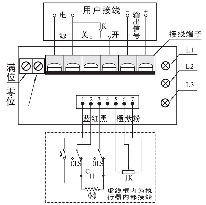
- Adjustable potentiometer:
- The "full position" and "zero position" are used to adjust the corresponding output current to 20mA or 4mA when the valve is fully open or fully closed.
- Indicator light:
- L1: Red, power indicator, illuminates when the bit generator is connected to power;
- L2: Green, lighted when valve is open for operation;
- L3: Green, lighted when valve is closed for operation;
3, debugging and setup
- Potentiometer center position determination
- Output Current Correction
- The position generator has been calibrated at the factory and generally does not need to be adjusted by the user. If the output current is not 20mA or 4mA when the valve is fully open or fully closed, and the error is greater than 1%, then it needs to be adjusted, and can be corrected as follows: Connect a 20mADC ammeter to the output signal terminal, fully close the valve, adjust the "zero" potentiometer with a small screwdriver, and observe the ammeter display, and when the output is greater than 4mA, slowly rotate clockwise, and vice versa, slowly rotate counterclockwise until the ammeter displays 4mA (). When the output is greater than 4mA clockwise direction slowly rotate, and vice versa, then counterclockwise direction slowly rotate until the ammeter shows 4mA ( ± 0.02); the valve is fully open, with a small screwdriver to adjust the "full position" potentiometer, observe the ammeter display, when the output is greater than 20mA counterclockwise direction slowly rotate, and vice versa, then clockwise direction slowly rotate, and the ammeter display, when the output is greater than 20mA, then clockwise direction slowly rotate, then clockwise direction slowly rotate, then clockwise direction slowly rotate, then clockwise direction slowly rotate. When the output is greater than 20mA, rotate slowly in counterclockwise direction, and vice versa, rotate slowly in clockwise direction until the ammeter shows 20mA (±0.02), and the output current correction is completed.
Note: The output current correction must be adjusted to the "zero position" first and then to the "full position", otherwise it will cause the position generator to malfunction.


 Egong.com.cn 42018502006527 No.