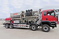
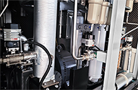


After connecting the DCL electric actuator to the power supply (AC380V, AC220V, AC24V, DC24V), the DCS can control the actuator through the control signals (analog, switching, bus, IoT) to drive the electric valve to full open, full close or specified opening degree. Thus, the temperature and flow of the fluid process,stressesand other parameters for open or closed loop control.
How does a switching electric actuator work?
How do regulated electric actuators work?
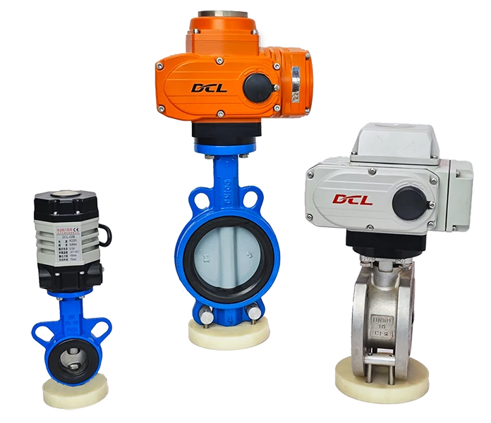
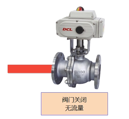
Switching electric actuator
When you install a switching electric actuator (valve) on your pipeline, you can control your electrically operated valve with a relay, switch, or PLC (DCS) along the way to open or close the fluid.
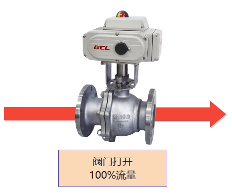
Status of switching electric actuators
Control via relay - AC220V
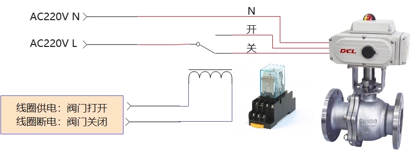
- When the L line is switched to the OFF input terminal through the relay, the actuator drives the valve closed. When driven to the fully closed position, the actuator stops driving and the motorized valve remains fully closed.
- When the L line is switched to the open input terminal through the relay, the actuator drives the valve open. When driven to the fully open position, the actuator stops driving and the motorized valve remains in the fully open position.
- If the power supply to the AC220V L line stops while the actuator is driving the valve, the actuator stops driving and the motorized valve maintains its current position.
- When the actuator you selected is equipped with a heated dehumidifier, keep the power supply on the AC220V L line after driving the actuator to the fully open/closed position.
NOTE: The above circuit diagram shows the function of a switching actuator (motorized valve) in its simplest form. In practical applications, additional protection devices such as fuses and current limiters should also be considered.
Control via relay - DC24V
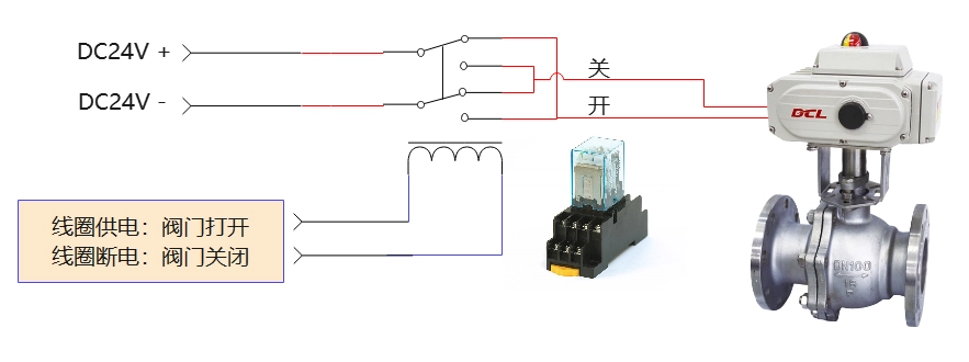
- When the power + line is switched to the open input terminal and the power - line is switched to the close input terminal by means of a relay, the actuator drives the valve open. When driven to the fully open position, the actuator stops driving and the motorized valve remains fully open.
- When the power + line is switched to the OFF input terminal and the power - line is switched to the OPEN input terminal via a relay, the actuator drives the valve closed. When driven to the fully closed position, the actuator stops driving and the motorized valve remains fully closed.
- If the power supply to the power line stops while the actuator is driving the valve, the actuator stops driving and the motorized valve maintains its current position.
- When you select an actuator configured with a heated dehumidifier, keep the power supply powered after driving the actuator to the fully open/closed position.
NOTE: The above circuit diagram shows the function of a switching actuator (motorized valve) in its simplest form. In practical applications, additional protection devices such as fuses and current limiters should also be considered.
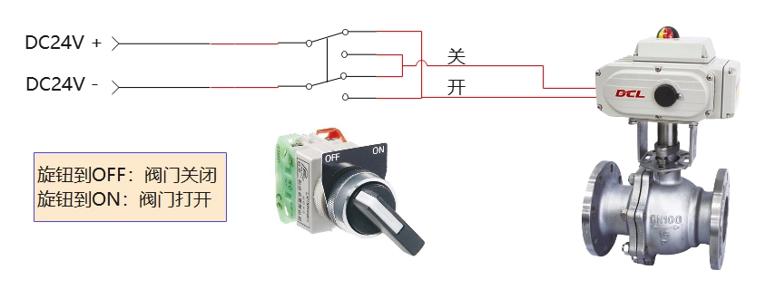
Control by mechanical switch - AC220V
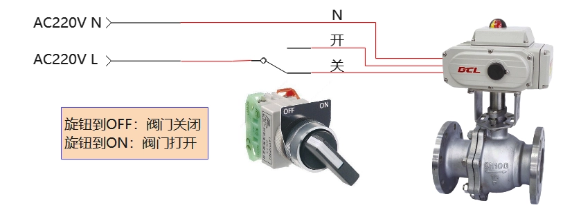
- When the L line is switched to the OFF input terminal by a mechanical switch, the actuator drives the valve closed. When driven to the fully closed position, the actuator stops driving and the motorized valve remains fully closed.
- When the L line is switched to the open input terminal by a mechanical switch, the actuator drives the valve open. When driven to the fully open position, the actuator stops driving and the motorized valve remains in the fully open position.
- If the power supply to the AC220V L line stops while the actuator is driving the valve, the actuator stops driving and the motorized valve maintains its current position.
- When the actuator you selected is equipped with a heated dehumidifier, keep the power supply on the AC220V L line after driving the actuator to the fully open/closed position.
NOTE: The above circuit diagram shows the function of a switching actuator (motorized valve) in its simplest form. In practical applications, additional protection devices such as fuses and current limiters should also be considered.
Control via mechanical switch - DC24V
- When the power + line is switched to the open input terminal and the power - line is switched to the close input terminal by a mechanical switch, the actuator drives the valve to open. When driven to the fully open position, the actuator stops driving and the motorized valve remains fully open.
- When the power + line is switched to the OFF input terminal and the power - line is switched to the ON input terminal by a mechanical switch, the actuator drives the valve closed. When driven to the fully closed position, the actuator stops driving and the motorized valve remains fully closed.
- If the power supply to the power line stops while the actuator is driving the valve, the actuator stops driving and the motorized valve maintains its current position.
- When you select an actuator configured with a heated dehumidifier, keep the power supply powered after driving the actuator to the fully open/closed position.
NOTE: The above circuit diagram shows the function of a switching actuator (motorized valve) in its simplest form. In practical applications, additional protection devices such as fuses and current limiters should also be considered.
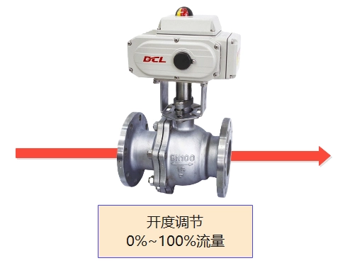
Regulating electric actuator
When you install the DCL regulated electric actuator (valve) on the pipeline, you can control the opening of the valve through the analog signal of 4~20mA, 0~10V, bus (Modbus, CAN, Profibus, DeviceNet, Foundation Fieldbus, HART, Ethernet) or Internet of Things. Thus realizing the function of regulating fluid flow.
Status of regulated electric actuators
Control via 4-20mA
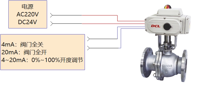
- The actuator adjusts the valve opening according to the 4~20mA input signal in a linear relationship; 4mA corresponds to the valve fully closed and 20mA corresponds to the valve fully open.
- When the input signal is out of range, the actuator enters the lost signal mode. Depending on the user setting, the actuator drives the valve to fully open, fully close, or maintains the position of the valve at the time of the loss of signal.
NOTE: The above circuit diagram shows the function of a switching actuator (motorized valve) in its simplest form. In practical applications, additional protection devices such as fuses and current limiters should also be considered.
Controlled by 2-10V
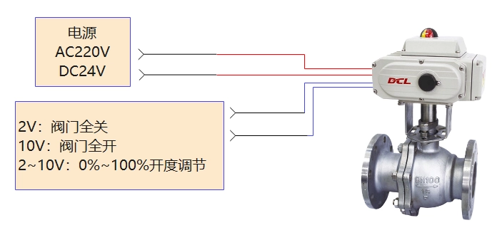
- The actuator adjusts the valve opening according to the 2~10V input signal in a linear relationship; 2V corresponds to the valve fully closed and 10V corresponds to the valve fully open.
- When the input signal is out of range, the actuator enters the lost signal mode. Depending on the user setting, the actuator drives the valve to fully open, fully close, or maintains the position of the valve at the time of the loss of signal.
NOTE: The above circuit diagram shows the function of a switching actuator (motorized valve) in its simplest form. In practical applications, additional protection devices such as fuses and current limiters should also be considered.
Control via bus
- Modbus, CAN, Profibus, DeviceNet, Foundation Fieldbus, HART, Ethernet
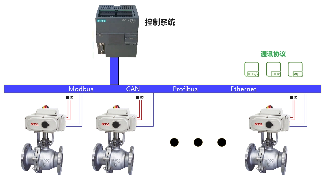
- The control system sends opening control commands to the actuator through the bus communication protocol. The actuator follows the bus command to drive the valve to the specified opening.
- If a bus error occurs, the valve is actuated to fully open, fully close, or maintain the valve position at the time of the bus error, depending on the user setting.
- If the power supply to the power line stops while the actuator is driving the valve, the actuator stops driving and the motorized valve maintains its current position.
NOTE: The above circuit diagram shows the function of a switching actuator (motorized valve) in its simplest form. In practical applications, additional protection devices such as fuses and current limiters should also be considered.
Controlled through the Internet of Things
- NB-Iot, LoRA, LoRaWAN, 4G

- Through the actuator IoT platform, users can send opening control commands to the actuator via computer and cell phone APP. After the actuator receives the command from the IOT platform, it drives the valve to the specified opening degree.
- Based on the actuator IoT platform, monitoring and recording of key factors such as actuator valve position, torque, energization duration, regulation frequency, etc. can also be realized under safety requirements or extreme application scenarios.
- You can also troubleshoot actuators that have deployed non-IoT functionality. This application is extremely useful for monitoring and troubleshooting occasional faults in actuator applications.
- If the power supply to the power line stops while the actuator is driving the valve, the actuator stops driving and the motorized valve maintains its current position.
NOTE: The above circuit diagram shows the function of a switching actuator (motorized valve) in its simplest form. In practical applications, additional protection devices such as fuses and current limiters should also be considered.


 Egong.com.cn 42018502006527 No.