


1、Mount the actuator to the valve body
Correctly install the electric actuator on the valve body according to the requirements of "Installation of Actuator and Valve Body", and manually operate the actuator to check whether the operation is normal.
2. Adjustment of the all-off mechanical limit
First actuate the valve to the fully closed position with the handle and make sure that the mechanical limit stops do not hit the adjusting screws or the case at this time, then loosen the scale plate locking screws, adjust the scale plate so that the pointer is at the 0 scale line on the scale plate (at SHUT), and tighten the scale plate locking screws.
3. Adjustment of fully open mechanical limit
Then use the handle to drive the valve to the fully open position and make sure that the mechanical limit stops are not hitting the adjusting screws or box at this time. If the valve travels at an angle of 90°, the pointer should be at the 0 mark on the indicator (at OPEN) at this time.
Special Tip:
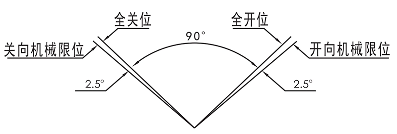
- If there is no special requirement, the travel angle between the fully closed position and fully open position of the actuator is 90° at the factory commissioning. If the fully closed and fully open positions of the valve and the actuator are not the same after the valve is equipped by the user, it is necessary to re-adjust the valve, and the mechanical limits must be adjusted in accordance with the requirements of the following figure.
- All adjustable (E-type) opening potentiometers have taken into account the possibility of shifting the potentiometer working area due to changes in the fully open and fully closed positions during valve commissioning, so it is generally not necessary to adjust the potentiometers and gears.
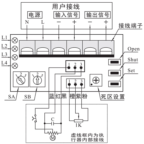
- The wiring of the terminals must be connected correctly according to the following diagram to avoid damage to the servo controller, in particular, pay attention to: Never connect the "Power" line to the "Input Signal" or "Output Signal" terminals. terminal.
4、Servo controller panel description
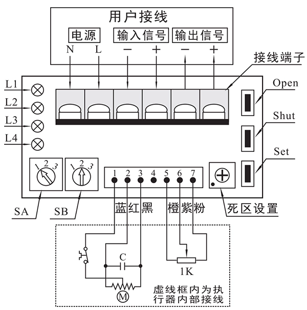
keystrokes
- Open. In the "set state" (i.e. the arrow of the selector switch SA is pointing to "2") press this key to operate the actuator in open mode, release the key to stop the motor, and press Set and Open at the same time to calibrate the fully open position.
- Shut. Pressing this key in the "setup state" causes the actuator to run in the OFF position; releasing this key stops the motor; pressing Set and Shut at the same time is used to calibrate the full OFF position.
- Set. In the "setup state", it works with Open and Shut to realize specific functions.
selector switch
- SA. To select the input signal positive and negative mode and setting status, the positive and negative setting must be set in the power-on state to be effective, and the arrow direction corresponds to the function as follows (set to 1 at the factory).
1 –positive effect 2-Setup Status 3 –opposite reaction
- SB. Selects the processing method when the input signal fails, and the arrow points to the corresponding function as follows (set to 2 at the factory).
1-Valve fully open 2 –Valve stays in place 3-Valve fully closed
Deadband value setting potentiometer
Used to set the deadband value. Potentiometer opening from 1-10, corresponding to the deadband value 0.5%-5.0% (factory deadband value is set to 1.5%).
indicator light
- L1. Green, power indication, servo controller power terminal N, L indirectly connected to the power light;
- L2. Red, Input Signal Failure Fault Indication, Lights up when the input signal fails;
- L3. Red, position detection circuit fault indication, open potentiometer lead open circuit, short circuit, itself damaged when the light is on;
- L4. Red: jamming fault indication, light comes on when jamming occurs.
5. Settings
If the arrow of selector switch SA points to position "2″, it enters the setting state. In the setting state, it is possible to carry out travel calibration, selection of input signal failure processing method, deadband value setting, manual operation and output current correction.
Stroke Calibration
- Full-closed position calibration: by pressing the Open and (or) Shut buttons to adjust the valve to the full closed position, first press the Set button and do not let go, and then press the Shut button, the two buttons at the same time to keep pressed for about 4S clock, when the indicator light L2 is bright, and at the same time, release the Shut and Set buttons, L2 is off, the full-closed position calibration is complete.
- Full open position calibration: by pressing the Open and (or) Shut buttons to adjust the valve to the fully open position, first press the Set and do not release, and then press the Open key, the two keys at the same time to keep pressed for about 4S clock, when the indicator light L2 is bright, and at the same time, release the Open and Set buttons, L2 is off, the full open position calibration is complete.
Input signal failure processing method selection
Selector switch SB is used to select the input signal failure mode: 1-valve fully open 2-valve hold in place 3-valve fully closed.
Note: Selector switch SB is still effective when the change is made under automatic operation (i.e., when selector switch SA is dialed to "1″ or "3″).
Deadband value setting
The deadband setting potentiometer turns clockwise to increase the deadband value, and counterclockwise to decrease the deadband value. There is a scale on the front side of the potentiometer, and every time the potentiometer is rotated by one degree, the deadband value changes by 0.5%. When the deadband value is set to less than 0.5%, the servo controller will process it according to 0.5%.
The valve can be opened and closed manually by pressing Open or Shut in the setting state.
6. Operation
Setting the selector switch SA to position "1" or "3" enters the automatic operation state. At this time, the actuator opening and output signals change according to the input signal.
Notes:
- Reaction, the input current is 4mA corresponds to the opening degree of the valve position is 100%, at this time the output current is 20mA; input current is 20mA corresponds to the opening degree of the valve position is 0%, at this time the output current is 4mA.
- Servo controller accuracy level 1, the basic error does not exceed ± 1%, back less than 1%
| 输入信号 | 4mA | 8mA | 12mA | 16mA | 20mA |
|---|---|---|---|---|---|
| 指针位置 | CLOSE (0) | 2.5 | 5 | 7.5 | OPEN (0) |
| 阀门位置 | 0% | 25% | 50% | 75% | 100% |
| 输出电流 | 4mA | 8mA | 12mA | 16mA | 20mA |
7、 Output current correction
The servo controller has been calibrated for the output current at the factory, and generally does not need to be adjusted by the customer. If the output current is not 4mA when the valve is fully closed or 20mA when the valve is fully open, and the error is greater than 1%, then it needs to be adjusted, and it can be corrected as follows:
In the output current terminal access to a 20mADC ammeter, the selector switch SA to the "2" position, into the setup state. Press the Set button, and then at the same time, press Open, Shut two keys, when the L2 light at the same time after the release of the three keys, that is, into the 4mA calibration. Observe the ammeter display, press the Open key when the current increases, press the Shut key when the current decreases, the output current will be adjusted M4.00mA (± 0.02). Press Set to turn off, keep Set pressed, wait for L2 to light up again, release the key, the 4mA calibration is completed, and automatically enter the 20mA calibration. Observe the ammeter display, use the Open and Shut keys to adjust the current to 20.00mA (±0.02). Press Se to optimize L2 off, keep Se under acid, wait for L2 to light up again, release the key, the output current correction is completed and L2 is off.
8, fault judgment and treatment
A malfunction occurs, the malfunction indicator light is on, and different indicators are on to represent different malfunctions.
L2 Bright
- If the input signal is less than 5mA or more than 22mA, the servo controller considers the input signal invalid. Measure the voltage between the input signal terminals, when the input signal is 4~20mA, the voltage between the two ends of the input signal terminals should be between 0.88~4.4V (the resistance of the two ends of the input signal is 220Q), if the input signal is less than 0.55V (the current should be 2.5mA) or more than 4.84V (the corresponding current should be 22mA), it means that there are open circuits, short circuits, leakage phenomenon or the signal given by the control system has errors. If the input signal is less than 0.55V min - should current 2.5mA or more than 4.84V (corresponding current 22mA), then it means that the input signal lead has open circuit, short circuit, leakage phenomenon occurs or the signal given by the control system is wrong.
L3 bright
- Indicates a fault in the position detection circuit. Check the opening potentiometer bow I line for open circuit, short circuit or damage to the potentiometer itself. Normal potentiometer voltage should be about 4V, potentiometer center line and either end of the voltage should be changed with the potentiometer opening degree changes, if the above checks are normal, 13 is still on, it may be a servo controller failure.
L4 Bright
- Indicates a mechanical failure in operation. Check whether the motor wiring is loose or open circuit; whether the motor itself can work normally; rotate the actuator in two directions with the handle to check whether the actuator is jammed, if the above checks are normal and the light is on, it may be a servo controller failure.
The actuator opening does not correspond to the opening given by the input signal or does not travel the full stroke.
- The deadband setting potentiometer circuit on the servo controller is faulty.
The output current does not correspond to the valve opening.
- If the opening potentiometer is damaged or the leads are open or short-circuited, the output current does not correspond to the valve opening, and the L3 lamp lights. If the potentiometer circuit is excluded, and the output current cannot be corrected to correspond to the valve opening, the servo controller should be faulty.


 Egong.com.cn 42018502006527 No.