


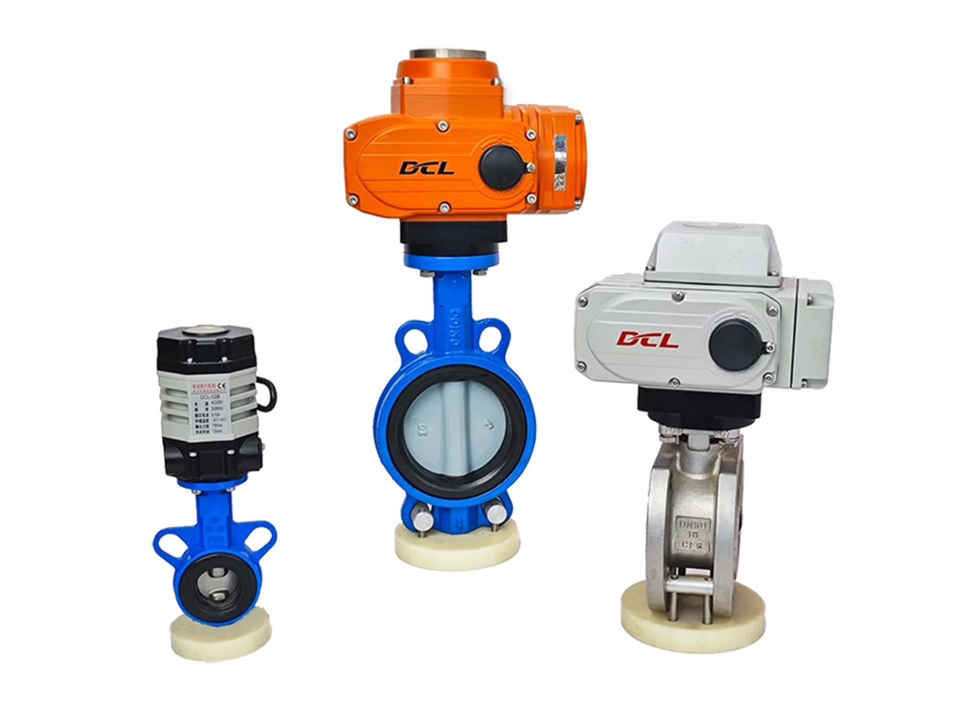

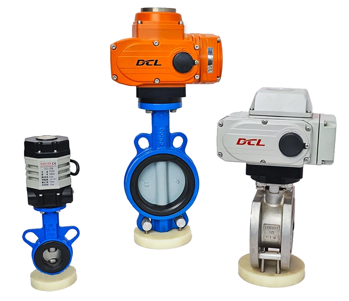
This guide applies to DCL explosion-proof series/general series/quick-open series modulating actuators with the following model numbers:
- General Series: DCL-02GEY/DCL-05GEY/DCL-10GEY/DCL-20GEY/DCL-40GEY/DCL-60GEY
- Explosion-proof Series: DCL-Ex05GEY/DCL-Ex10GEY/DCL-Ex20GEY/DCL-Ex40GEY/DCL-Ex60GEY
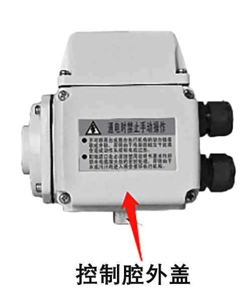
1、Open the outer cover of the control cavity
Use a Phillips-type screwdriver to unscrew the 4 fastening screws on the outer cover of the control chamber.
2、Check the status of the fault indicator
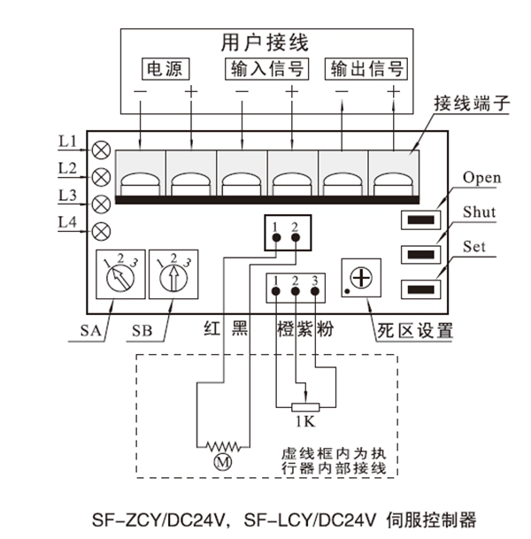
Keeping the power on, check the fault indicator of the actuator control module (Model: SF-ZCY):
- L1:Green:Power indication, servo controller power supply terminal -, + indirectly connected to the power supply when the light is on;
- L2:Red:Input signal failure fault indication, the lamp lights up when the input signal fails;
- L3:Red:Position detection circuit fault indication, open potentiometer lead open circuit, short circuit, itself damaged when the lamp lights;
- L4:Red:Jamming fault indication, light comes on when jamming occurs.
Description of fault judgment logic:
- L2 Bright:If the input signal is less than 2.5mA or greater than 22mA, the servo controller considers the input signal invalid. Measure the voltage between the input signal terminals, when the input signal is 4~20mA, the voltage between the two ends of the input signal terminals should be between 0.88~4.4V, if the input signal is less than 0.55V (corresponding to a current of 2.5mA) or greater than 4.84V (corresponding to a current of 22mA), it means that the input signal lead is open, short circuit, leakage phenomenon occurs or control system to give the signal. If the voltage between the terminals is normal and L2 is still on, the servo controller may be faulty.
- L3 is lit:Indicates a fault in the position detection circuit. Check whether the opening potentiometer lead is open or short circuit or whether the potentiometer itself is damaged. Normal potentiometer voltage should be about 4V, potentiometer center line and either end of the voltage should change with the potentiometer openness changes, if the above checks are normal, L3 is still bright, may be servo controller failure.
- L4 is lit:Indicates a mechanical failure in operation. Check whether the motor wiring is loose or open circuit; the motor itself can work properly; with the handle hand crank the actuator were rotated in both directions, check whether the actuator is jammed, if the above checks are normal, L4 is still bright, may be servo controller failure.
3. Signal measurement
- Measure the DC24V power supply voltage to determine whether there are fluctuations and voltage drops in the power supply of the actuator on site. The output torque of the actuator will become smaller under negative pressure, and it may not be able to drive the valve.
- Measure the voltage between the input signals - and +.
- Measure the voltage between - and + of the output signal.
- Give an external signal and measure the DC24V power supply voltage while the actuator is running. (Confirm the drive capability of the DC24V power supply, and the voltage drop across the cable.)
When you are troubleshooting at the project site, you can contact our technical service personnel at the first time to troubleshoot and determine the solution together.
Tel: 13026331611 (Mr. Chen)


 Egong.com.cn 42018502006527 No.