

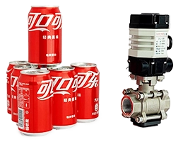
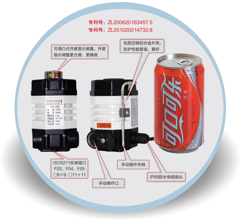
Ultra-compact electric actuator
- Coke size for more compact installation
- High-strength die-cast aluminum alloy for greater protection.
- High EMI performance.
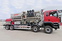
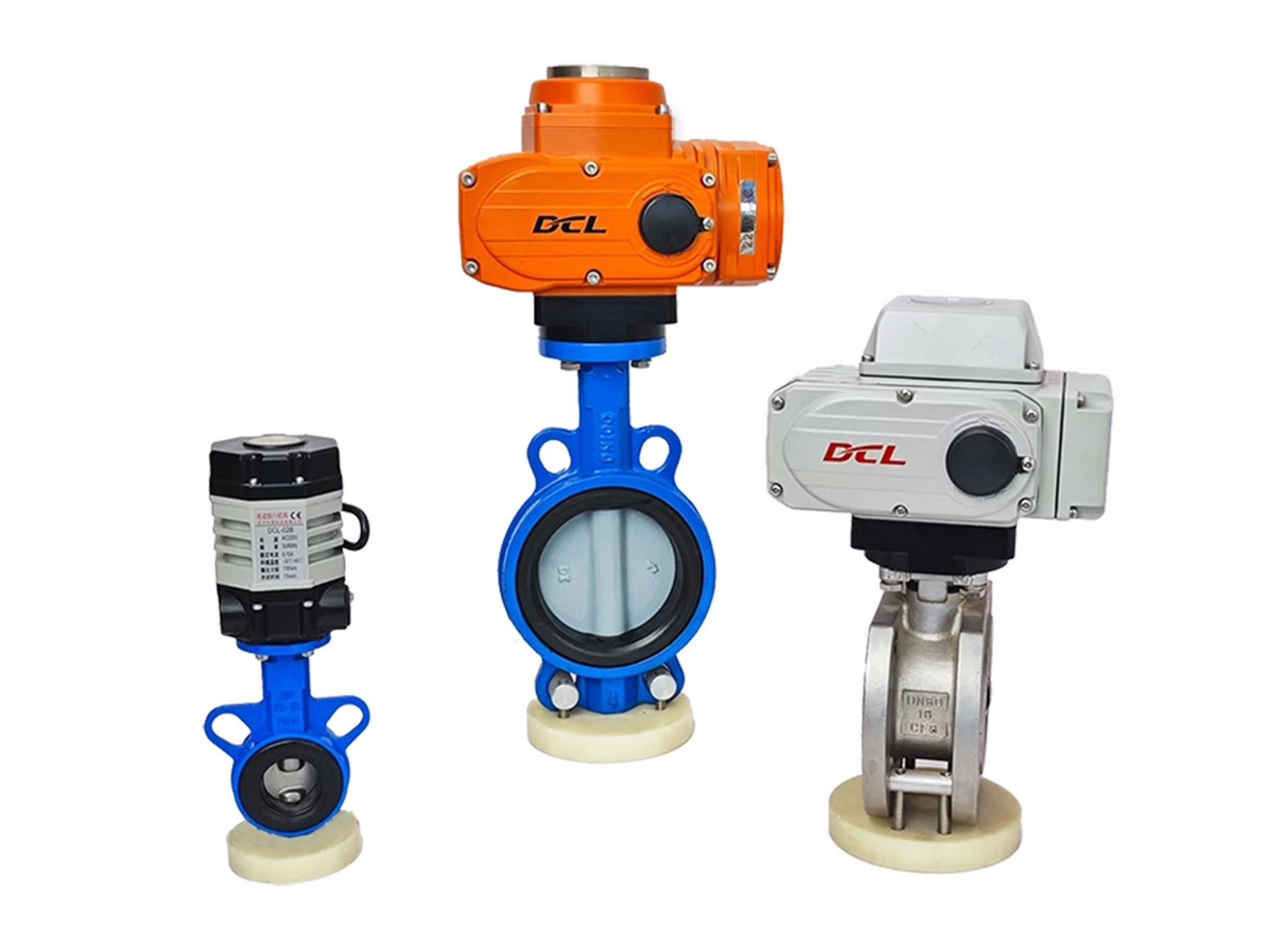
Adaptive Valve
Partial rotation
damper
0~270°
Torque/Time
9~18Nm
7~60S
Type of control
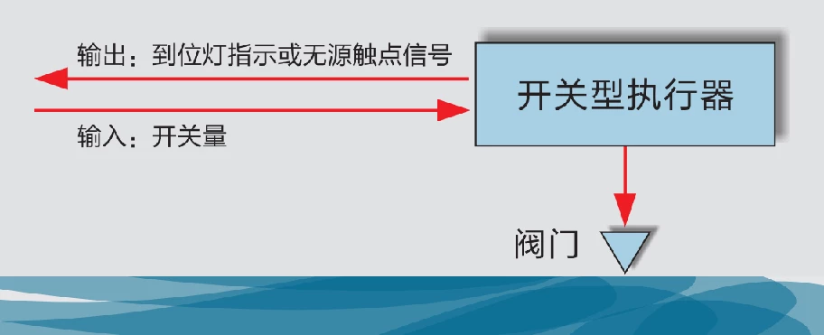
switching type
regulating type
Supply Voltage
DC24V
AC110V
AC220V
Input/Output Signal
4~20mA
0~10V
Level | Contacts
Modbus-RTU
optional
Self-heating dehumidification
Adjustment method
regulating type
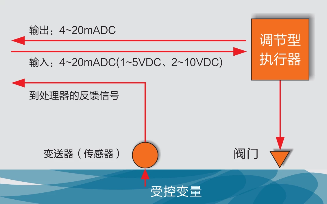
The servo controller is placed inside the actuator and receives commands from the central control system to drive the valve to the appropriate opening position based on changes in the controlled variables in the pipeline (flow, pressure, temperature, level).
Adopting S4 intermittent type working system, the working frequency is up to 1200 times per hour.
switching type
A, B, G type control circuits
Switching models have only fully open and fully closed limit positions; intermediate positions can be preset if desired (B, G models). Upon receipt of a command, the actuator will drive the valve to the fully open, fully closed, or intermediate position.
The S2 short-time type working system is adopted, and the continuous running time does not exceed 15 minutes.
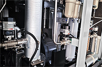
Functional Features
electrical machinery
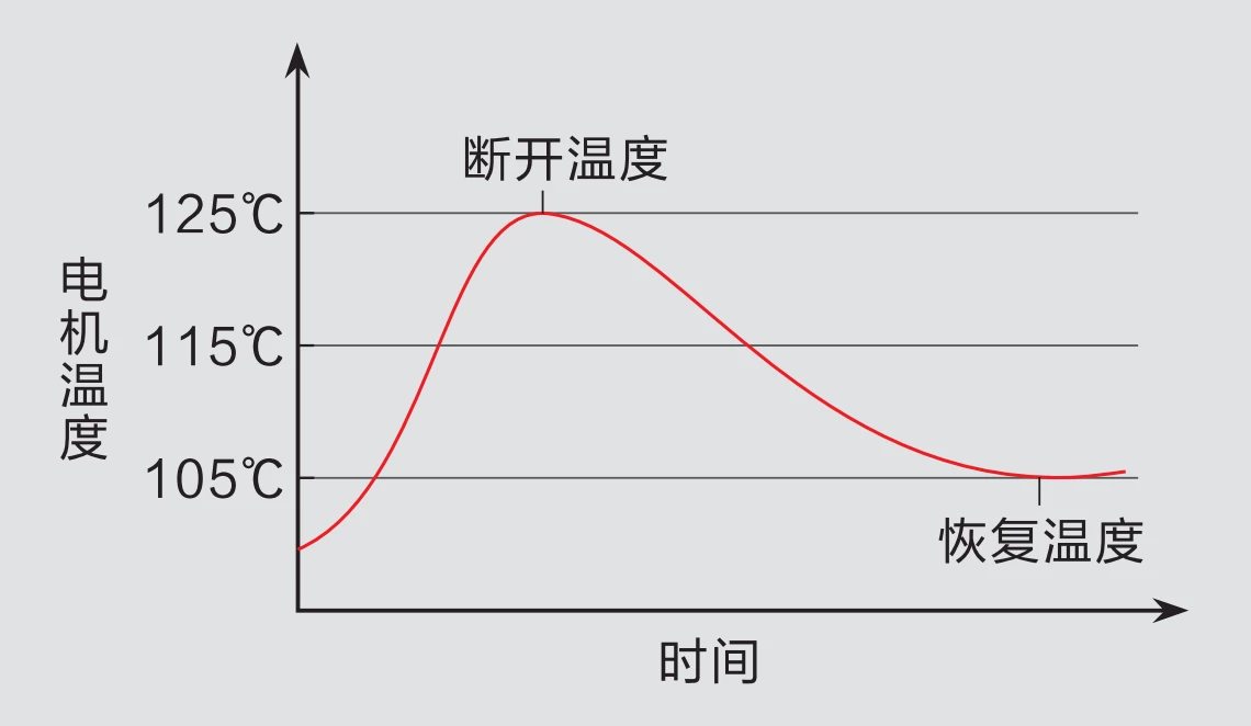
Due to the working characteristics of the valve, the actuator is required to have the ability to start at full load in the opening, closing and any intermediate position of the valve, which requires the motor of the actuator to have a high starting torque. This requires the actuator motor to have a high starting torque, and at the same time, due to the need for opening adjustment, the motor is required to have a small moment of inertia.DCL series electric actuator motors are specially designed to meet these requirements.
When the actuator is blocked, the temperature of the motor will rise rapidly. When the motor temperature rises to 125°C, a PTC thermal protector placed in the motor windings cuts the circuit to protect the motor and the control system. When the motor temperature drops to 90-105℃ whenThe circuit will come back on.
Electrical and mechanical limits
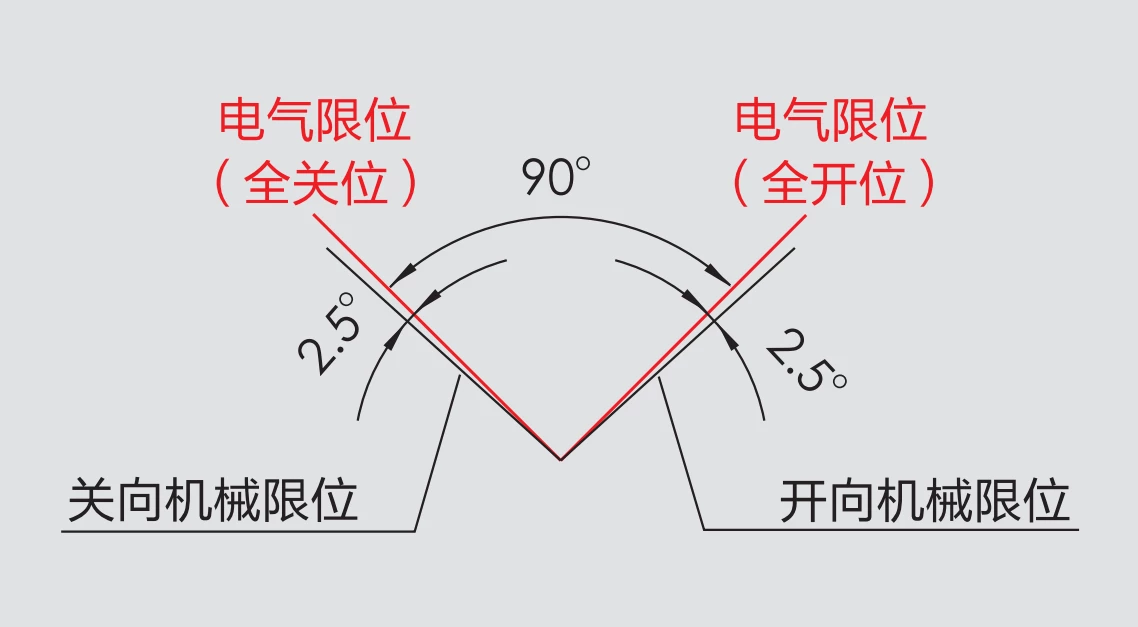
Electrical travel limit function: When the actuator reaches the fully open or fully closed limit position or the set intermediate position, the built-in electrical limit switch will cut off the circuit to protect the actuator.
Output Shaft Mechanical Limit Function: When the electrical travel limit function fails, the output shaft of the actuator will be locked by the mechanical limit device, thus protecting the valve from damage.
The diagram shows the positional relationship between the electrical and mechanical limits.
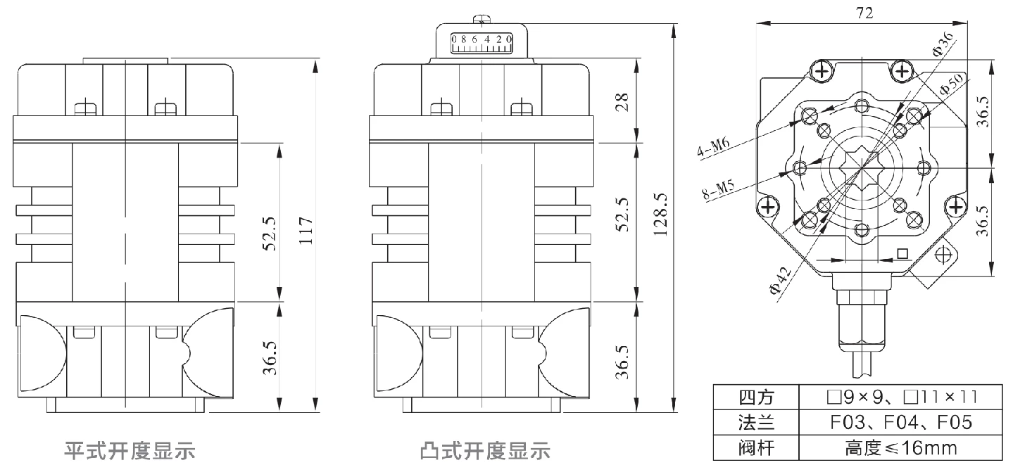
Dimensions
Technical Parameters
| 电源 | DC24V, AC24V, AC110V, AC220V |
| 标准力矩/时间 | 18Nm/15S |
| 可选力矩/时间 | 9Nm/7S, 18Nm/60S |
| 回转角度范围 | 0~90° |
| 电机功率/电流 | DC24V:8W / 0.7A AC24V:6W / 1.3A AC110V: 6W / 0.3A AC220V:6W / 0.15A |
| 可选控制电路 | DC24V: E型/G型 AC24V: A型/B型 AC110V/AC220V: A型/B型/E型 |
| 整机重量 | 1.2kg |
| 绝缘电阻 | DC24V/AC24V:100MΩ/250VDC AC110V/AC220V:100MΩ/500VDC |
| 耐压等级 | DC24V/AC24V:500VAC 1 分钟 AC110V/AC220V:1500VAC 1 分钟 |
| protection class | IP67 |
| 安装方位 | 360°任意角度安装 |
| 电气接口 | 7芯电缆连接 |
| 环境温度 | -25℃ ~ +55℃ |
| 保险丝选用 | DC24V:2A AC24V:3A AC110V/AC220V:1A |
| DCL-02 调节型 控制参数 | |
|---|---|
| 输入信号 | 4~20mA, 0~10V任意标定 |
| output signal | 4~20mA, 0~10V任意标定 |
| computer bus | 485/Modbus/CAN |
| 物联网 | WIFI/LoRA/4G |
| 基本误差 | ≤±1% |
| 回查 | ≤1% |
| 死区 | 自适应死区,定制 |
| 阻尼特性 | 0次 |
| 机构重复性误差 | ≤1% |
control circuit
Type A: with limit position switches (active contacts)
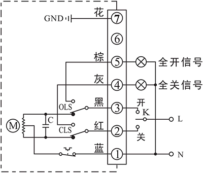
Through the switching circuit to realize the "on", "off" operation, and output a set of full open and full closed active signal.
Wiring Instructions:
1. Terminal 1 is connected to the center line of the power supply;
2、 Power supply phase line and terminal 2 connected for "off" operation;
3. The power supply phase line is "on" when it is connected to terminal 3;
4, power supply phase line and terminal 2 connected and "off" operation in place, terminal 4 connected to the "full off signal" indicator light;
5, power supply phase line and terminal 3 connected and "open" operation in place, terminal 5 connected to the "full open signal" indicator light;
6. Terminal 7 Ground wire.
Type B: with intermediate position switch (passive contact)
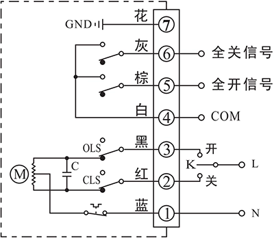
Through the switching circuit to realize the "on", "off" operation, and output a set of full open and full closed passive signal.
Wiring Instructions:
1. Terminal 1 is connected to the center line of the power supply;
2、 Power supply phase line and terminal 2 connected for "off" operation;
3. The power supply phase line is "on" when it is connected to terminal 3;
4. Terminal 4 is the common terminal of passive contact;
5. When "open" operation is in place, terminal 5 outputs "full open signal".
6、When the "OFF" operation is in place, the terminal will program the "Full Off Signal";
7. Terminal 7 ground wire.
Type E: with servo controller (regulated)

Input: 4~20mA / 0~10V Any configuration.
Output: 4~20mA / 0~10V Any configuration.
Bus: Modbus / CAN
Internet of Things: WIFI/LoRA/4G DTU
Wiring Instructions:
1. "N" of the "Power" input is connected to the center line, and "L" is connected to the phase line;
2, "Input signal" end connects to the negative pole of the input signal, "+" connects to the positive pole of the input signal;
The "output signal" end is connected to the negative terminal of the DC ammeter, and the "+" is connected to the positive terminal of the DC ammeter.
Type G: DC control circuit with passive contact switches
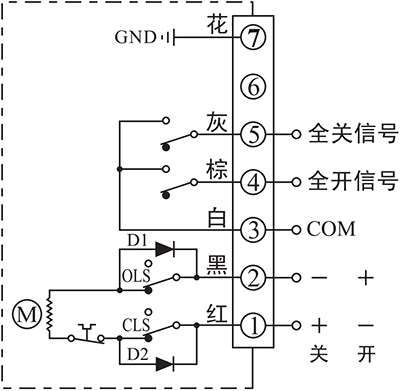
According to the unidirectional conductivity of the diode, by reversing the positive and negative poles of the DC power supply, it realizes the "on" and "off" operation and outputs a set of passive signals of full on and full off.
Wiring Instructions:
Terminal 1 is connected to the positive pole of the power supply, and terminal 2 is connected to the negative pole of the power supply for "off" operation; lemon 2 is connected to the positive pole of the power supply, and terminal 1 is connected to the negative pole of the power supply for "on" operation;
2、 Terminal 3 is the common terminal of passive contact;
3. When the "open" operation is in place, the terminals confirm the "full open signal".
4、When "Off" operation is in place, terminal 5 outputs "full off signal".
5. Terminal 7 Ground wire.


 Egong.com.cn 42018502006527 No.